Method for controlling advancing mechanism

A technology for controllers and conveyors, which is applied in the direction of earth drilling, mining equipment, mine roof support, etc., and can solve problems such as inability to determine the angle, inability to control the inclination of the scraper, knocking down, etc.

Inactive Publication Date: 2011-04-27
MARCO SYSTEMANALYSE UND ENTWICKLUNG GMBH
View PDF4 Cites 4 Cited by
  • Summary
  • Abstract
  • Description
  • Claims
  • Application Information

AI Technical Summary

Problems solved by technology

First of all in the lower and smaller supports used in mines (where the coal seam often has a seam thickness of only one meter), it is only very difficult or impossible to measure the reed tube based on the size and diameter defined by the piston. The rod is installed in the push mechanism jack
In addition, because the reed pipe measuring rods are installed in the moving jack, these reed pipe measuring rods are located at the height of the support base on the other hand, that is, they barely pass the bottom, and there is also a danger that they will pass through the bottom of the mining position when the support moves. The rocky material will damage or knock down the electrical interface of the reed switch measuring rod
[0006] The use of a distance measuring system in the jack for controlling the swing mechanism, in fact, has the additional disadvantage that only the distance between the support and the conveyor can be determined here, but not the distance formed between the two. angle
This means that the inclination of the individual scrapers, which typically occurs during conveyor movement, cannot be controlled and can thus lead to damage at the connecting parts of the individual conveyor components if the permissible angular dimensions are exceeded

Method used


Image

  • Method for controlling advancing mechanism
  • Method for controlling advancing mechanism
  • Method for controlling advancing mechanism

Examples


Embodiment Construction

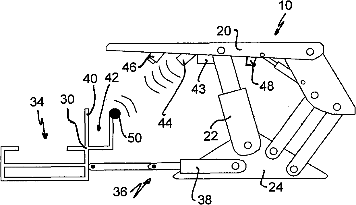
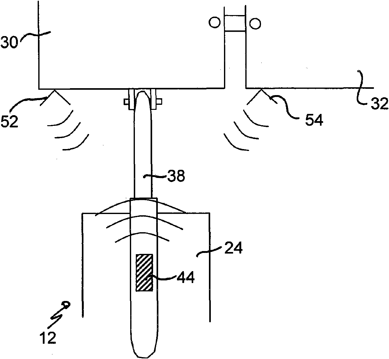
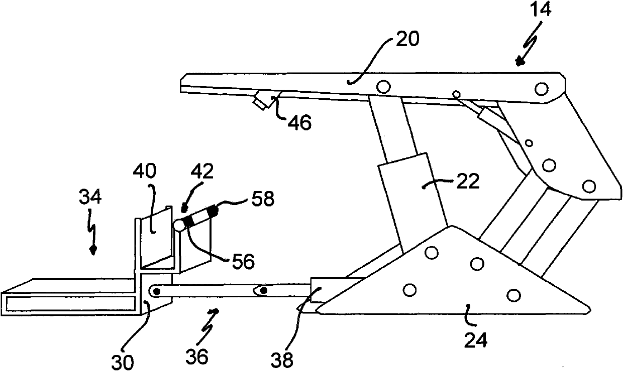
[0028] figure 1 A first embodiment of the shed-type combined support 10 is schematically shown, the top cover 20 of which is connected to the base 24 through the pillars 22 . By a plurality of scrapers 30,32 (see figure 2 ) Conveyor 34 of composition is connected with shed type combination support 10 in a known manner by stepping mechanism 36, and wherein stepping mechanism has moving jack 38. Each scraper 30 , 32 of the conveyor 34 has a vertical stop 40 on the side facing the shed combination 10 , on the back of which a cable and line channel 42 is connected.

[0029] In addition, the shed combination support 10 is equipped with an electrohydraulic controller 43 in a known manner, which is arranged between the pillars 22 on the underside of the roof 20, and which and the central working surface controller (not shown) out) connected. Furthermore, an ultrasonic sensor 44 and a camera 46 are located on the underside of the roof 20 , the ultrasonic sensor 44 being arranged i...


PUM


Abstract

The present invention relates to a method for controlling an advancing mechanism in an underground operation surface frame, wherein the distance between a conveyor and a shed type combined frame is measured through a sensor.

Description

technical field [0001] The invention relates to a method for controlling a walking mechanism in an underground working face support. Background technique [0002] For the automated operation of face supports in underground coal mining, it is necessary to continuously control the position of the conveyor and the individual supports or shed-type supports. Shed-type composite supports support the excavation site against the pressure of the top layer and enable the movement of the conveyor through the coal seam. The electro-hydraulic controlled supports are connected to the conveyor via push jacks. The conveyor consists of individual parts (scraper Schuessen), which can be connected to one another via hinges and can be inclined vertically or horizontally to one another by a defined angular dimension. During mining the conveyors on each shed block move a predetermined amount in the direction of the coal roadway wall (kohlesto β) according to the passage of the mining equipment ...

Claims


Application Information

Patent Timeline
Patent Type & Authority Applications(China)
IPC IPC(8): E21D23/14E21D23/08
CPCE21D23/12E21D23/0056E21D23/0034E21D2023/144E21D23/144
Inventor 马丁·路透
Owner MARCO SYSTEMANALYSE UND ENTWICKLUNG GMBH
Why Eureka
Try Eureka