Illuminating beam shaping system

A technology of lighting beams and beams, applied in lighting devices, lighting and heating equipment, components of lighting devices, etc., can solve the problems of weakening and reducing the working effect, and achieve the effect of avoiding refraction loss

Inactive Publication Date: 2011-04-27
金展精技工业有限公司 +1
View PDF5 Cites 7 Cited by
  • Summary
  • Abstract
  • Description
  • Claims
  • Application Information

AI Technical Summary

Problems solved by technology

[0006] The above-mentioned existing technologies are all shaped at the position of the cover body of the light emitting surface of the lamp to finally solve the effect of light diffusion, but the working components are far away from the light source, so after the photon energy has been weakened by the square of the distance , and then perform commutation refraction operation, at this time its working effect will be reduced due to the greatly weakened energy. The reason for the reduction is also limited by the conditions of the refractive index of the innate refraction components

Method used


Image

  • Illuminating beam shaping system
  • Illuminating beam shaping system
  • Illuminating beam shaping system

Examples


Embodiment Construction

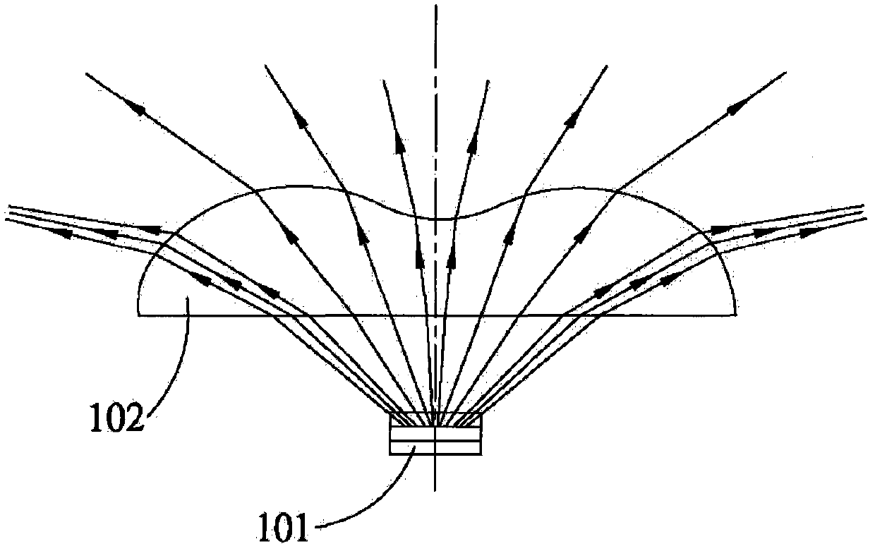
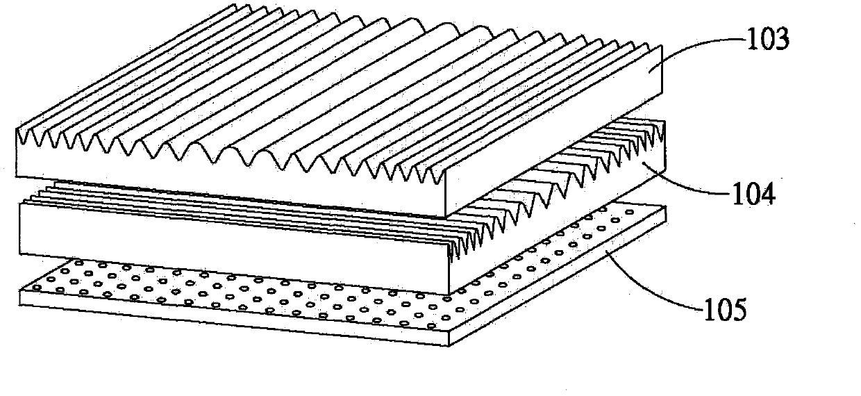
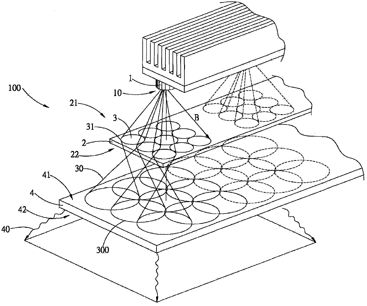
[0032] The beam shaping system of the present invention is especially used for similar laser chips, the total light quantity of which is divided into a plurality of groups of conical beams through the pre-segmentation means, and the actual optical surface of the bottom of the cone beams acts synchronously on an optical diffusion After the component is refracted and diffused by the optical diffusion component, a more uniform illumination brightness can be obtained on the light-emitting surface of the system. In the implementation description of this formula, the oblique reflection of the lens or spherical aberration is not considered, and it will be explained first.

[0033]The present invention will be described in detail below in conjunction with the accompanying drawings. As a part of this description, the principle of the present invention will be described through embodiments. Other aspects, features and advantages of the present invention will become clear at a glance throu...


PUM


Abstract

The invention relates to an illuminating beam shaping system, in particular to an illuminating beam shaping system which can achieve uniform illuminating brightness on the emergent surface of an illuminating system. In the invention, a splitting device is used, and all beams from a laser chip are sequentially subject to a pre-positioned splitting means and a post-positioned diffusion means, so that uniform illuminating brightness can be achieved on the optical irradiation surface of the system. The splitting device comprises array type curved lenses, the input side of the splitting device is aligned within the range of the included angle of emergent beams from the laser chip, the beams can be converted into multi-array tapered beams at the output side of the splitting device in accordance with different arrangement positions and refraction angles of the lenses, and the tapered-bottom practical optical surface of each tapered beam acts on a optical diffusion assembly and is subject to refraction and diffusion, so that a uniform illuminating brightness can be achieved on the emergent surface of the system.

Description

technical field [0001] The invention relates to an illumination beam shaping system, in particular to an illumination beam shaping system capable of emitting uniform illumination brightness on the exit surface of the illumination system. Background technique [0002] According to the type of lighting system, there are long-range projection, near-end lighting, substrate backlight and traffic signal light display. At present, due to the maturity of LED technology, the main reason is that the particle size is small and the angle of light emission is easy to standardize, forming a pointable For permanent lighting applications, or small spaces that only require low-power auxiliary lighting and are widely used, they have already occupied a place in illuminators, and the modulation of wavelength and color temperature is becoming more and more visually acceptable. Although it cannot completely replace the traditional situational aesthetics Cultural lamps and lanterns, but because LE...

Claims


Application Information

Patent Timeline
Patent Type & Authority Applications(China)
IPC IPC(8): F21V5/04F21V5/08F21V17/00
Inventor 魏清伟
Owner 金展精技工业有限公司
Why Eureka
Try Eureka