Lateral air supply and return treatment cabinet layout of refrigerator safety performance testing room and method thereof

A technology of air treatment and safety performance, which is applied in the field of return air air treatment cabinets in refrigerator test laboratories, to achieve the effect of meeting wind speed, meeting temperature and humidity requirements, wind speed requirements, and uniform air

Inactive Publication Date: 2011-04-27
ELECTROMECHANICAL PRODS DETECTING TECH CENT OF SHANGHAI ENTRY EXIT INSPECTION & QUARANTINE BUREAU
View PDF2 Cites 3 Cited by
  • Summary
  • Abstract
  • Description
  • Claims
  • Application Information

AI Technical Summary

Problems solved by technology

However, when the length and width of the refrigerator test room have been determined, and the length direction of the refrigerator test room plus the width of the air supply and return air handling cabinet cannot meet the determined size conditions, the only way to reduce the number of stations for the refrigerator to be tested The number to meet its symmetrical layout
Therefore, it is necessary to solve the problem of building a refrigerator performance test room with the same length and width as the above without or cannot meet the usual conditions.

Method used


Image

  • Lateral air supply and return treatment cabinet layout of refrigerator safety performance testing room and method thereof
  • Lateral air supply and return treatment cabinet layout of refrigerator safety performance testing room and method thereof
  • Lateral air supply and return treatment cabinet layout of refrigerator safety performance testing room and method thereof

Examples


Embodiment Construction

[0016] The present invention will be further described below in conjunction with the accompanying drawings and embodiments.

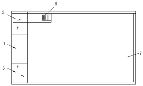
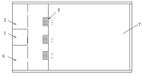
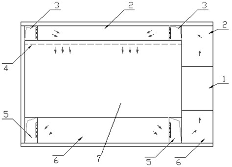
[0017] like image 3 , shown in 4, the side of the refrigerator safety performance testing room of the present invention sends and returns the wind air treatment cabinet layout, comprises air treatment cabinet 1, environmental test room 7, sends and returns air main pipe 2,6, sends and returns air branch pipe 3,5 , air supply orifice 4.

[0018] The air treatment cabinet 1 is installed on the side of the environmental test chamber 7, and the upper and lower air supply and return air main pipes 2, 6 are symmetrically arranged on the upper and lower sides of the environmental test room 7, and the air supply and return air main pipes 2, 6 are respectively connected to the outlet and air inlet of the air treatment cabinet 1 . The air supply and return main pipes 2, 6 are out of the air treatment cabinet 1, and the air supply and return air branch pipes 3,...


PUM


Abstract

The invention relates to a lateral air supply and return treatment cabinet layout of a refrigerator safety performance testing room and a method thereof. The lateral air supply and return treatment cabinet layout of the refrigerator safety performance testing room comprises an air treatment cabinet and an environmental test chamber, wherein the air treatment cabinet is arranged on a side face of the environmental test chamber; the environmental test chamber is provided with a master air supply pipe and a master air return pipe which are symmetrically arranged up and down; and the master air supply pipe and the master air return pipe are connected with an air outlet and an air inlet of the air treatment cabinet respectively. The method comprises the following steps of: allowing air to flow through a coil pipe of the air treatment cabinet under the action of a fan in the air treatment cabinet; matching an evaporation coil pipe of the air treatment cabinet with an automatic control electric heating pipe for use to control air outlet temperature; distributing air to each air supply branch pipe after the air flows through the master air supply pipe; uniformly supplying the air into the environmental test chamber through an air supply perforated plate; gathering the ventilated air to the master air return pipe through air return branch pipes; and allowing the air to flow through the coil pipe in the air treatment cabinet to adjust temperature so as to finish circulation. Compared with the prior art, the layout and the method solve the problem of site limitation and meet the requirements of temperature, humidity and air speed inside the testing room at the same time.

Description

technical field [0001] The invention relates to a refrigerator test laboratory air return air treatment cabinet, in particular to the layout of the return air air treatment cabinet and the wind speed distribution method of the test laboratory in the household refrigerator safety and energy efficiency comprehensive test system. Background technique [0002] At present, the test condition control of the conventional refrigerator test laboratory is realized through the air supply and return air treatment cabinet installed in the outer center of the longitudinal top. This method can ensure that the temperature, humidity and wind speed distribution in the test chamber meet the requirements of the series standards of GB / T 8059 "Household Refrigeration Appliances". That is, it is realized by symmetrical layout in the width direction, see figure 1 , 2 Examples: Air handling cabinet 1, air supply main pipe 2, return air main pipe 6, environmental test chamber 7, orifice plate 8. Th...

Claims


Application Information

Patent Timeline
Patent Type & Authority Applications(China)
IPC IPC(8): F24F3/00F24F13/02
Inventor 傅培刚李瑛徐胜
Owner ELECTROMECHANICAL PRODS DETECTING TECH CENT OF SHANGHAI ENTRY EXIT INSPECTION & QUARANTINE BUREAU
Why Eureka
Try Eureka