A kind of preparation method of optical fiber preform rod

A technology of optical fiber preform and liner, applied in glass manufacturing equipment, manufacturing tools, etc., can solve problems such as uneven distribution and complex doping process, reduce optical fiber attenuation, reduce equipment use costs, and evenly distribute alkali metal content Effect

Active Publication Date: 2018-11-23
YANGTZE OPTICAL FIBRE & CABLE CO LTD
View PDF6 Cites 0 Cited by
  • Summary
  • Abstract
  • Description
  • Claims
  • Application Information

AI Technical Summary

Problems solved by technology

Document US9250386B2 puts alkali metal raw materials into the inner wall of the glass tube, heats the outer wall of the glass tube, and diffuses alkali metal oxides into the glass, so that the attenuation of the optical fiber at 1550nm can reach below 0.17dB / km The alkali metal doped by this heating diffusion method forms a concentration gradient on the inner and outer walls of the glass, and the distribution is uneven
文献US20140127507A1,US9229160B2,CN102627400B,CN102603179A,CN102627398A,CN103502164A,CN104093674A,CN102617033A,CN103502164A和CN102730977A,均通过连续移动的热源加热玻璃管内的碱金属原料,通过扩散在玻璃管内壁掺入碱金属,掺杂工艺复杂

Method used


Image

  • A kind of preparation method of optical fiber preform rod
  • A kind of preparation method of optical fiber preform rod
  • A kind of preparation method of optical fiber preform rod

Examples


Embodiment 1

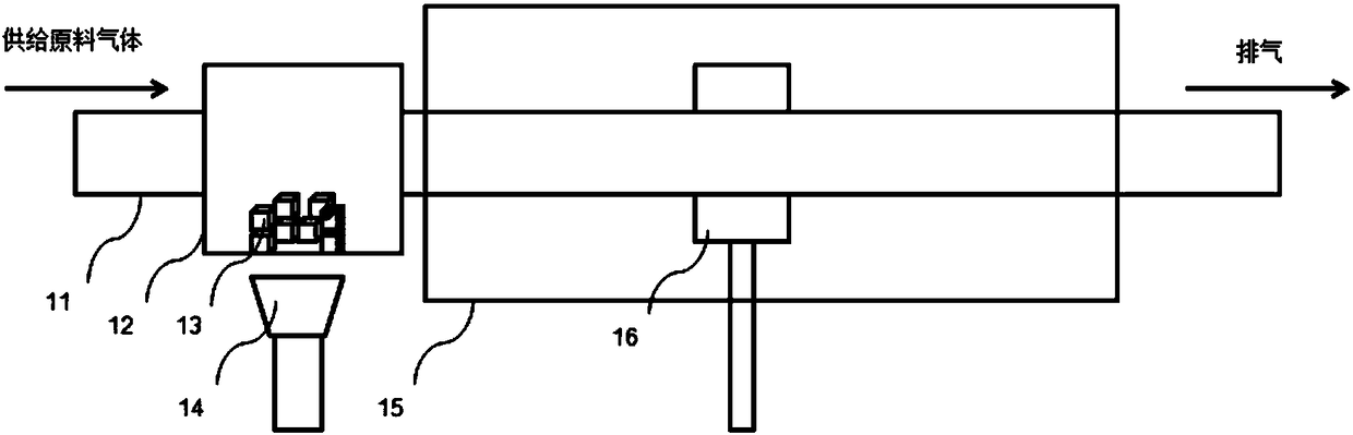
[0031] Such as figure 1 As shown, the optical fiber preform is manufactured through the PCVD deposition process, the holding furnace 15 surrounds the deposition reaction area of ​​the glass liner 11, and the resonant cavity 16 is between the holding furnace 15 and the glass liner 11, and can move left and right on the periphery of the glass liner 11 , to provide a heat source for the deposition reaction area; a large-diameter glass tube 12 is connected in series at the gas inlet end of the glass liner 11, and the two ends of the large-diameter glass tube 12 are respectively connected to the gas inlet pipe and the glass liner 11 by welding, and A heater 14 is installed around the outside of the large-diameter glass tube 12;

[0032] use as figure 1 The device, the method for preparing an optical fiber preform, the steps are as follows:

[0033] 1) Put 5-50g of alkali metal raw material KBr13 in the large-diameter glass tube 12;

[0034] 2) Mandrel cladding deposition: turn o...

Embodiment 2

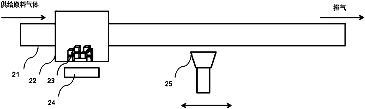
[0041] Such as figure 2 As shown, the optical fiber preform is manufactured by the MCVD deposition process, and the blowtorch 25 can move left and right along the glass liner 21 to provide a heat source for the deposition reaction area; a large diameter glass tube 22 is connected in series at the inlet end of the glass liner 21, and the The two ends of the large-diameter glass tube 22 are respectively connected to the inlet pipe and the glass liner 21 by welding, and a heater 24 is installed around the outside of the large-diameter glass tube 22; the inner diameter of the large-diameter glass tube 22 is greater than that of the glass liner 21 the inside diameter of.

[0042] use as figure 2 The device, the method for preparing an optical fiber preform, the steps are as follows:

[0043] 1) 5-50g of alkali metal raw material NaBr23 is placed in the large-diameter glass tube 22;

[0044] 2) Mandrel cladding deposition: turn off the heater 24, the gas inlet end of the glass ...


PUM


Abstract

The invention discloses an optical fiber preform preparation method. A core layer and a part of coating layer of an optical fiber preform are manufactured by adopting an in-tube vapor deposition process. The optical fiber preform preparation method is characterized in that a large-diameter glass tube is serially connected to a gas inlet end of a glass lining tube, an alkali metal raw material is arranged in the large-diameter glass tube, a heater is arranged on the periphery of the large-diameter glass tube, the heater is turned off in the process of depositing for forming the coating layer, and coating layer raw material gas enters the glass lining tube and deposits to form the coating layer; in the process of depositing for forming the core layer, the heater is turned on, core layer raw material gas carrying the alkali metal raw material volatilized due to heating enters the glass lining tube and deposits to form the core layer. The alkali metal doping in the optical fiber preform preparation method is preformed in the core preform deposition process, the alkali metal content distribution is evener, the problem of uneven alkali metal distribution in the glass tube by adopting a diffusion process can be solved, and optical attenuation can be obviously reduced.

Description

technical field [0001] The invention relates to a method for preparing an optical fiber preform, belonging to the technical field of optical fiber communication. Background technique [0002] Optical fiber communication has the characteristics of large transmission capacity, long transmission distance, and fast transmission speed, and is widely used in optical communication networks such as long-distance trunk networks, metropolitan area networks, and access networks. Reducing the optical fiber attenuation coefficient can effectively increase the transmission distance of the optical fiber communication system, greatly reduce the number and cost of relay stations, and is of great significance for optimizing the structure of the transmission system and reducing operating costs. How to reduce the optical fiber attenuation coefficient has become a hot research topic for major optical fiber manufacturers. [0003] The existing technologies for reducing the optical fiber attenuat...

Claims


Application Information

Patent Timeline
Patent Type & Authority Patents(China)
IPC IPC(8): C03B37/018
CPCC03B37/01807
Inventor 陈刚朱继红汪洪海王瑞春艾靓
Owner YANGTZE OPTICAL FIBRE & CABLE CO LTD
Why Eureka
Try Eureka