Light source for optical automatic detector

An optical automatic and detector technology, applied in the direction of light source, point light source, scientific instrument, etc., can solve the problems that it is difficult to distinguish solder joints from the bottom plate, affect the accuracy of image analysis, etc., and achieve solder joint positioning and detection accuracy , easy control, simple light source structure

Inactive Publication Date: 2011-04-27
SOUTH CHINA UNIV OF TECH
View PDF3 Cites 13 Cited by
  • Summary
  • Abstract
  • Description
  • Claims
  • Application Information

AI Technical Summary

Problems solved by technology

[0003] In practical applications, the algorithm to achieve optical automatic detection is to search for color patches with the same size and color as the solder joints in the specified area to locate the solder joints. For circuit boards with obvious differences between the color of the bottom plate and the color of the solder joints, such as green and white Wait for the circuit board to be illuminated with a common light source, and then use this method for positioning. It is difficult to distinguish the solder joints from the bottom plate in terms of color, which will inevitably affect the accuracy of image analysis

Method used


Image

  • Light source for optical automatic detector
  • Light source for optical automatic detector
  • Light source for optical automatic detector

Examples


Embodiment 1

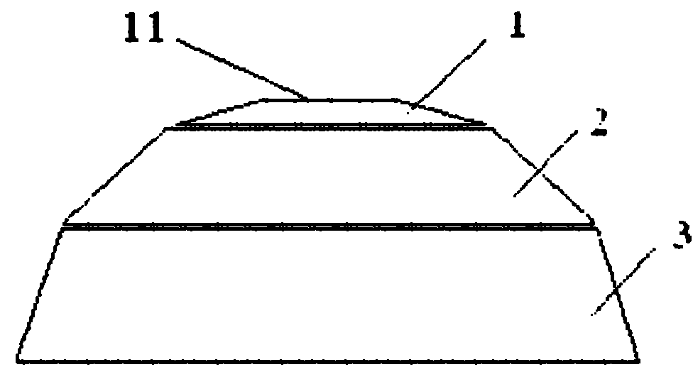
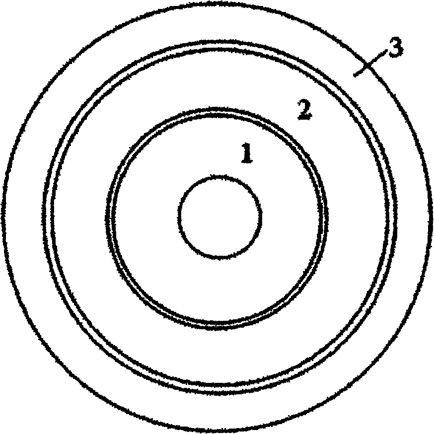
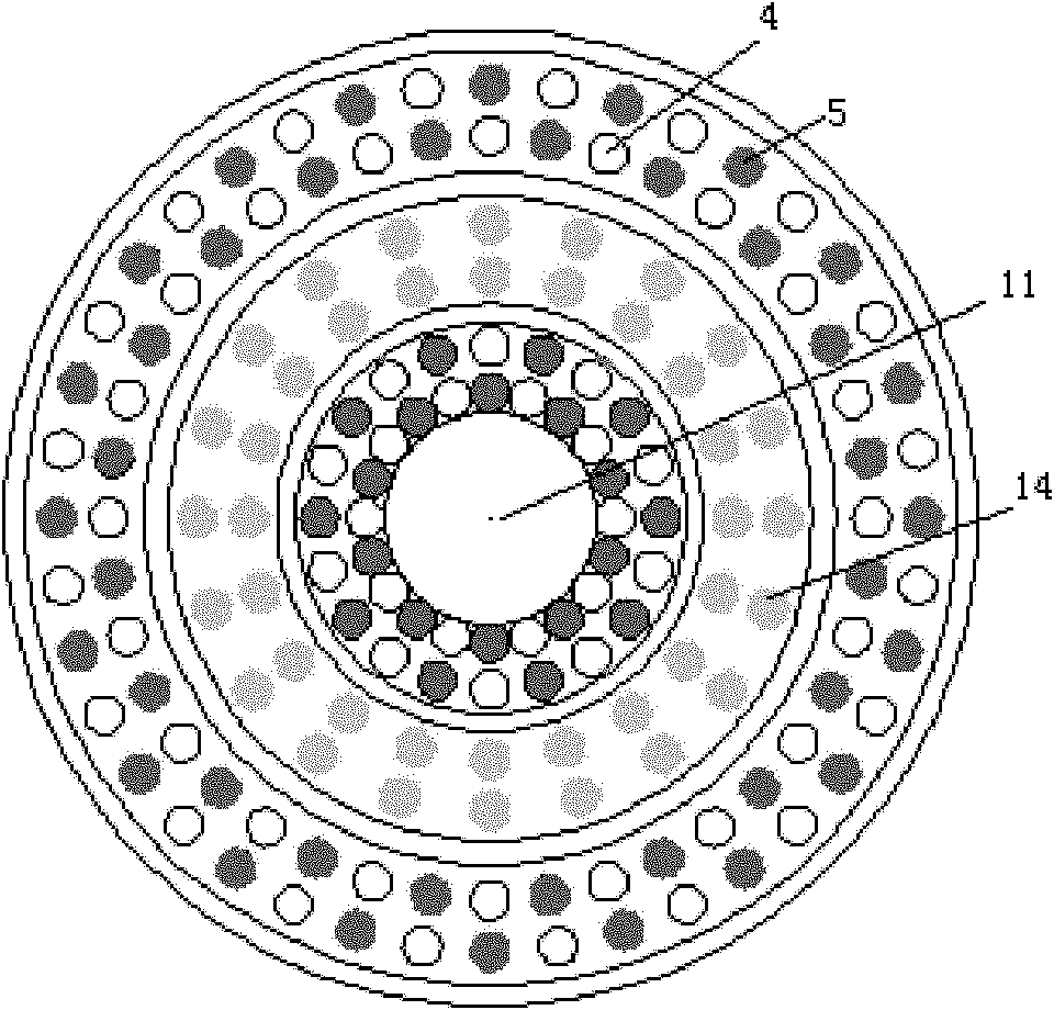
[0019] Such as figure 1 with figure 2 As shown, a light source for an optical automatic detector includes three annular LED arrays stacked coaxially in three layers and a middle through hole 11. The three annular LED arrays are all in the shape of a circular table, and the LED lights are embedded in the The inner side of the circular platform; one of the red and blue two-color circular LED array 1 is located on the top layer, which is used to provide high-angle lighting; one green circular LED array 2 is located on the middle layer, and is used to provide medium-angle lighting; the other red and blue two-color circular LED array 3 is located on the The bottom layer is used to provide low-angle lighting; each red and blue two-color annular LED array is divided into red and blue groups according to the LED color and connected to the external control device respectively, and the green annular LED array 2 is separately connected to the external control device; the external camera...


PUM


Abstract

The invention discloses a light source for an optical automatic detector. The light source comprises three annular LED arrays which are coaxially superposed in three layers and an intermediate through hole, wherein the three annular LED arrays are all shaped like a truncated cone, and an LED lamp is embedded at the inner lateral side of the truncated cone; two red-blue double-color annular LED arrays are respectively positioned in the top layer and the bottom layer and are used for providing high-angle and low-angle lighting; one green annular LED array is positioned in the intermediate layer and is used for providing intermediate-angle lighting; and each red-blue double-color annular LED array is divided into a red set and a blue set based on the LED color, the red set and the blue set are respectively connected with an external control device, the green annular LED array is independently connected with the external control device, and a lens is placed right above the intermediate through hole of the light source in the shooting process. By using the invention, the external control device can control the light source to select different colors of the light source in accordance with colors of circuit boards so as to achieve combined lighting effect, so that colors of tin solder images can be obviously different from those of base plate images. Besides, the light source has simple structure and is convenient to control.

Description

technical field [0001] The invention belongs to the field of light source design, in particular to a light source used for an optical automatic detector. Background technique [0002] In recent years, with the increase in the density of printed circuit boards and the miniaturization of components, optical automatic inspection instruments have gradually been widely used in the surface mount industry because they can effectively improve the speed and accuracy of defect detection. The main principle of the optical automatic detector is to collect and analyze the images of the objects that need to be detected on the circuit board, such as the component body, pins and solder joints, etc., to judge the effect of component placement and welding, and the collected images Good or bad plays a crucial role in the analysis results. The image acquisition device of the optical automatic inspection instrument is generally composed of an industrial camera and a light source, and the indust...

Claims


Application Information

Patent Timeline
Patent Type & Authority Applications(China)
IPC IPC(8): G01N21/956G01N21/01F21V19/00F21Y101/02
Inventor 邝泳聪张宪民刘奇亮梁经伦欧阳高飞
Owner SOUTH CHINA UNIV OF TECH
Why Eureka
Try Eureka