Liquid crystal dripping device

A liquid crystal dripping and liquid crystal technology, applied in the direction of measuring devices, instruments, optics, etc., can solve the problems of batch product quality, lower production capacity, high precision requirements, etc., to ensure product quality, avoid monitoring delays, and improve production capacity.

Inactive Publication Date: 2011-04-27
SHANGHAI TIANMA MICRO ELECTRONICS CO LTD
View PDF0 Cites 5 Cited by
  • Summary
  • Abstract
  • Description
  • Claims
  • Application Information

AI Technical Summary

Problems solved by technology

However, limited by the accuracy of the electronic balance, we can only weigh the total weight of 20 drops of liquid crystal each time to estimate the weight of each drop of liquid crystal, so it is impossible to accurately confirm the weight of each drop of liquid crystal dropped
Especially in small-sized products, only one or two drops of liquid crystal are dropped in each box, and the accuracy of the amount of each drop of liquid crystal is very high. At this time, the existing liquid crystal dropping device can no longer meet the requirements of precision control.
In addition, on the one hand, the existing liquid crystal dripping device cannot monitor the accuracy and stability of the liquid crystal dripping amount in real time, and there is a risk of quality problems in batch products
On the other hand, during the production process, the existing liquid crystal dropping device needs to stop production to weigh the liquid crystal dropping amount with an electronic balance, which affects the effective production time and reduces the production capacity

Method used


Image

  • Liquid crystal dripping device
  • Liquid crystal dripping device
  • Liquid crystal dripping device

Examples


Embodiment Construction

[0027] In order to make the purpose and features of the present invention more comprehensible, the specific implementation manners of the present invention will be further described below in conjunction with the accompanying drawings.

[0028] As mentioned in the background art, the existing liquid crystal dropping device cannot accurately confirm the amount of each drop of liquid crystal dropped, and cannot monitor the amount of liquid crystal dropped in real time, and will also affect the effective production time.
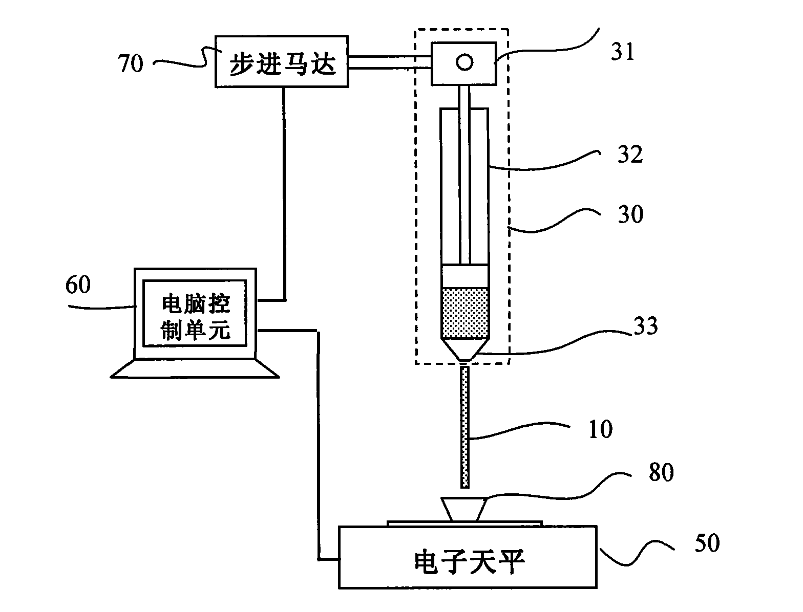
[0029] The core idea of ​​the present invention is that by arranging the emitting light unit and the receiving light unit on both sides of the dropping path of each drop of liquid crystal, each drop of liquid crystal will pass through and block the light between the emitting light unit and the receiving light unit when it drops, thereby The light-receiving unit outputs a changing signal, the light-receiving unit is connected to the signal processor, and the signa...


PUM


Abstract

The invention discloses a liquid crystal dripping device. The liquid crystal dripping device comprises a liquid crystal injector, a light emitting unit, a light receiving unit and a signal processor, wherein the liquid crystal injector is used for dripping and injecting liquid crystal into a liquid crystal panel; the light emitting unit and the light receiving unit are arranged on the two sides of a dripping path of each liquid crystal drop; and the signal processor is connected with the light receiving unit for monitoring the amount of dripped liquid crystal according to a signal output by the light receiving unit. In the liquid crystal dripping device, by arranging the light emitting unit and the light receiving unit on the two sides of the dripping path of each liquid crystal drop, each liquid crystal drop penetrates through and shields light between the light emitting unit and the light receiving unit during dripping, so that the light receiving unit outputs varying signals; and the light receiving unit is connected with the signal processor, and the signal processor is used for monitoring the amount of the dripped liquid crystal according to the signal output by the light receiving unit, so the amount of the liquid crystal is monitored in real time.

Description

technical field [0001] The invention relates to the technical field of plane display, in particular to a liquid crystal dropping device. Background technique [0002] Liquid Crystal Displays (LCDs) are widely used in electronic devices such as mobile phones, handheld computers, video cameras, and high-definition televisions. The basic structure of the liquid crystal display is as follows: figure 1 shown. figure 2 for figure 1 A cross-sectional view in the direction of A-A'. combine figure 1 with figure 2 , the liquid crystal display includes: a thin film transistor (Thin Film Transistor, TFT) substrate 1 and a color filter film (Color Filter, CF) substrate 2 facing apart from each other, and a closed loop for bonding the TFT substrate 1 and the CF substrate 2 Shaped sealant 3 , and a liquid crystal layer 4 formed between the TFT substrate 1 and the CF substrate 2 . The liquid crystal layer 4 is filled with liquid crystal and has spacer balls 5 with a certain density...

Claims


Application Information

Patent Timeline
Patent Type & Authority Applications(China)
IPC IPC(8): G02F1/1341G01G17/04
Inventor 王晓敏钟辉
Owner SHANGHAI TIANMA MICRO ELECTRONICS CO LTD
Why Eureka
Try Eureka