Display device and sliding structure thereof
A display device and sliding structure technology, applied in the direction of instruments, electrical digital data processing, digital data processing parts, etc., can solve the problems of small size, unable to watch, unable to meet the needs of users, etc., and achieve the effect of convenient use
- Summary
- Abstract
- Description
- Claims
- Application Information
AI Technical Summary
Problems solved by technology
Method used
Image

Examples
Embodiment Construction
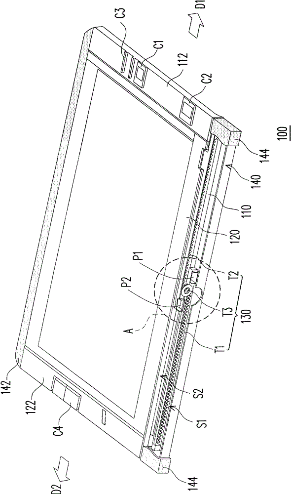
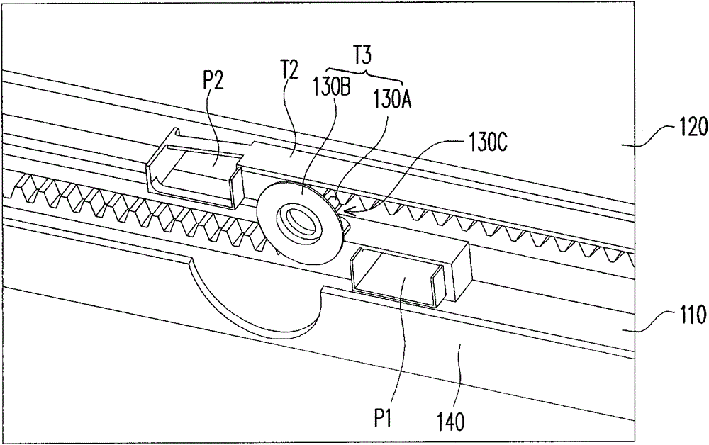
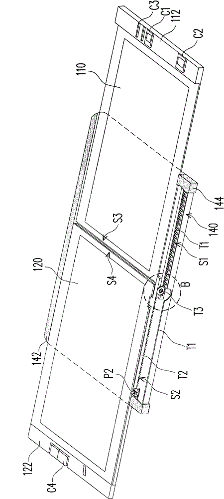
[0041] Figure 1A It is a schematic diagram of the double screen overlapping of the display device according to an embodiment of the present invention, and Figure 1B for Figure 1A Local enlarged view of the sliding structure in region A of . Figure 2A for Figure 1A The schematic diagram of the dual screen of the display device when unfolded, while Figure 2B for Figure 2A Local enlarged view of the sliding structure in region B of .
[0042] Please refer to Figure 1A and Figure 2A , the display device 100 is, for example, a flat display device, which includes a first display screen 110 and a second display screen 120 . The first display screen 110 and the second display screen 120 can use a liquid crystal display panel (LCD), a common one is a thin film transistor liquid crystal display panel (TFT-LCD), or a plasma display panel and an organic electroluminescent display panel (OELD). ) and other flat display panels, which have superior characteristics such as hi...
PUM
 Abstract
Description
Claims
Application Information
PatSnap Eureka turns technology decisions into work you can execute. Powered by our Innovation Knowledge Graph, it runs expert workflows across engineering, life sciences, materials and intellectual property. Get your review-ready output in minutes.


