
Accumulator fixing structure

A technology for fixing structures and batteries, applied in structural parts, battery pack parts, circuits, etc., can solve the problems of difficult electrical equipment maintenance, battery belt falling off, etc., to achieve effective parts configuration, reduce the number of parts, and improve maintainability.

Active Publication Date: 2011-04-27
HONDA MOTOR CO LTD
View PDF4 Cites 7 Cited by
  • Summary
  • Abstract
  • Description
  • Claims
  • Application Information

AI Technical Summary

Problems solved by technology

[0006] However, as mentioned above, in the case where the battery strap is formed with a U-shaped end, although there is an effect that the battery strap can be easily installed by using the U-shaped opening, there is a problem when the other end of the battery strap is detached and the battery strap is rotated. The battery strap may easily come off from the shaft from the open side of the U-shaped end, and as in Patent Document 1, there is a problem that it is difficult to hold the electrical equipment on the battery strap

Method used


Image

  • Accumulator fixing structure
  • Accumulator fixing structure
  • Accumulator fixing structure

Examples


Embodiment Construction

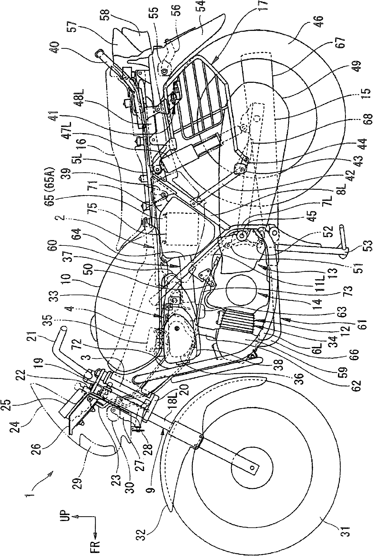
[0053] Hereinafter, embodiments of the present invention will be described with reference to the drawings. First, use figure 1A motorcycle 1 as an example of a vehicle to which the present invention is applied will be described. In the drawings used in the following description, the arrow FR indicates the front of the vehicle, and the arrow UP indicates the upper direction of the vehicle, and these directions are appropriately used in the following description.

[0054] The motorcycle 1 includes a frame 2, a head pipe 3 constituting a front end, a main frame 4 extending obliquely rearward and downward from the head pipe 3, and a pair of left and right seat rails extending rearward from the rear end of the main frame 4. 5L, 5R, a pair of left and right down frames 6L, 6R, the front end portion of the main frame 4 is generally downwards and then extended to the rear, the rear portion of the main frame 4 is obliquely rearward and downwards, and then extends downwards, and the re...


PUM


Abstract

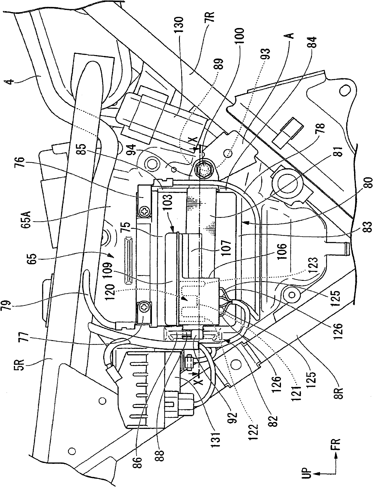
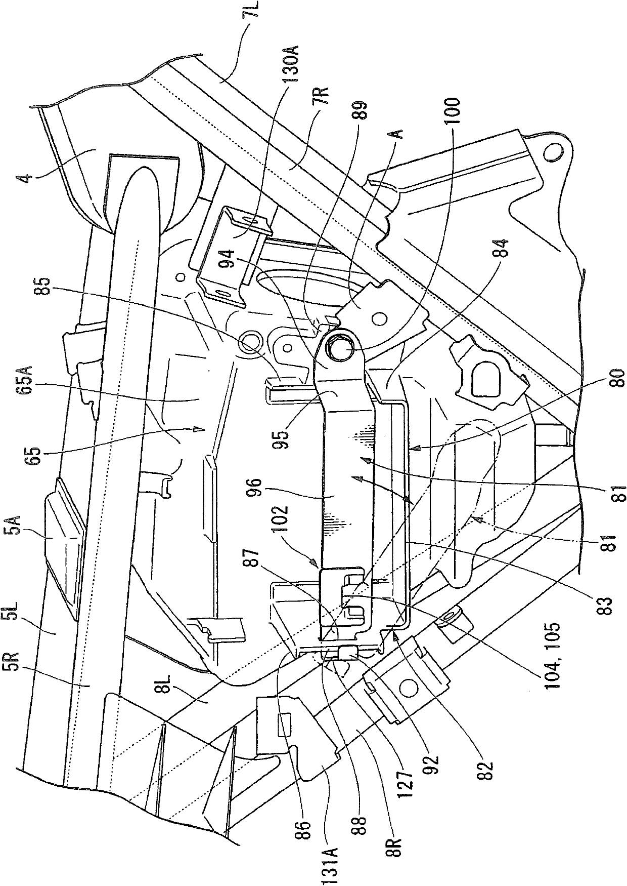
The invention provides an accumulator fixing structure. One end of an accumulator belt forms a U shape for the purpose of simplifying the part structure and preventing the accumulator belt from falling off. One end of the accumulator belt (81) forms a U-shaped clamping portion (92) which is folded into a U shape and is clamped with a shaft portion (88) formed on an accumulator box (80). In addition, a fuse box (103) for accommodating fuses is disposed on the accumulator belt (81) and is configured to be adjacent to the front end of the U-shaped clamping portion (92).

Description

technical field [0001] The present invention relates to a battery fixing structure for fixing a battery on a vehicle. Background technique [0002] In a vehicle such as a motorcycle, the battery is stably fixed using a rubber band formed in a belt shape or a plate made of metal or the like (hereinafter referred to as a battery belt). As such a battery belt, for example, Patent Document 1 discloses a structure in which a backup fuse holding mechanism for holding a backup fuse is integrally formed with a rubber belt. [0003] In addition, some of the above-mentioned battery straps have a structure having a hinge structure at one end and a fixing structure fixed by screws or fastened by bolts or the like at the other end. When using such a battery strap to fix the battery, it is conceivable that the hinge portion at one end of the battery strap is rotatably engaged with a battery box for accommodating the battery provided at an appropriate part of the vehicle, and the hinge po...

Claims


Application Information

Patent Timeline
Patent Type & Authority Applications(China)
IPC IPC(8): H01M2/10B60K1/04B60R16/04
CPCY02E60/12Y02E60/10
Inventor 安井永和松浦弘明
Owner HONDA MOTOR CO LTD
Learn More