Vibration damping and noise reducing mechanism for motor rotor

A motor rotor, vibration and noise reduction technology, applied in the direction of electromechanical devices, casings/covers/supports, electrical components, etc. problem, to achieve the effect of impact noise reduction

Active Publication Date: 2011-04-27
DONGGUAN GUOLIANG MOTOR
View PDF6 Cites 8 Cited by
  • Summary
  • Abstract
  • Description
  • Claims
  • Application Information

AI Technical Summary

Problems solved by technology

[0003] Generally, the rotor of the motor is directly socketed on the rotating shaft, and the rotating shaft is directly pivoted on the bracket. When the motor is running, since the AC power is used, the motor coil generates an alternating magnetic field with the alternating current. The alternating magnetic field causes the rotating rotor to vibrate in axial or radial pulses. After the whole rotor vibrates, it will collide with the support bearing. After a long time of use, it is very easy to damage the bearing and affect the service life of the entire motor. Moreover, the rotor vibrates against the support. It will produce a lot of noise, which will affect the comfort of using the motor to a certain extent.
At present, there are some motors with vibration reduction and noise reduction, mainly by installing a vibration reduction device at the pivot joint between the rotor and the base to absorb the radial vibration of the rotor to achieve the purpose of vibration reduction. This vibration reduction device is usually Although rubber gaskets, felt washers or a single spring can achieve a certain damping effect, it is difficult to control the size or the size of the elastic force, and it can only dampen vibrations in the radial direction, and the damping effect is not ideal.

Method used


Image

  • Vibration damping and noise reducing mechanism for motor rotor
  • Vibration damping and noise reducing mechanism for motor rotor
  • Vibration damping and noise reducing mechanism for motor rotor

Examples


Embodiment Construction

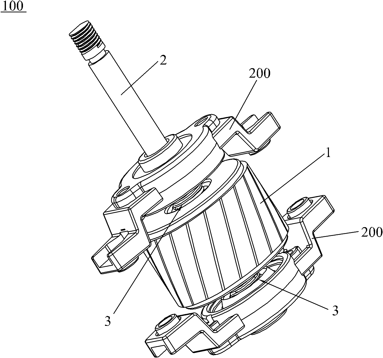
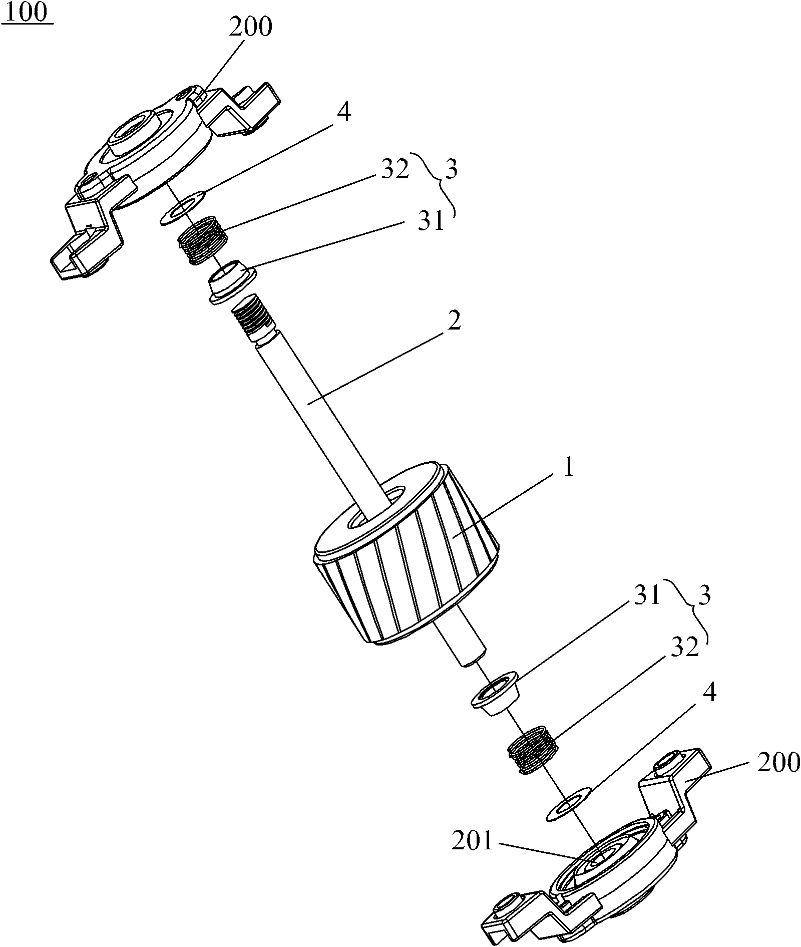
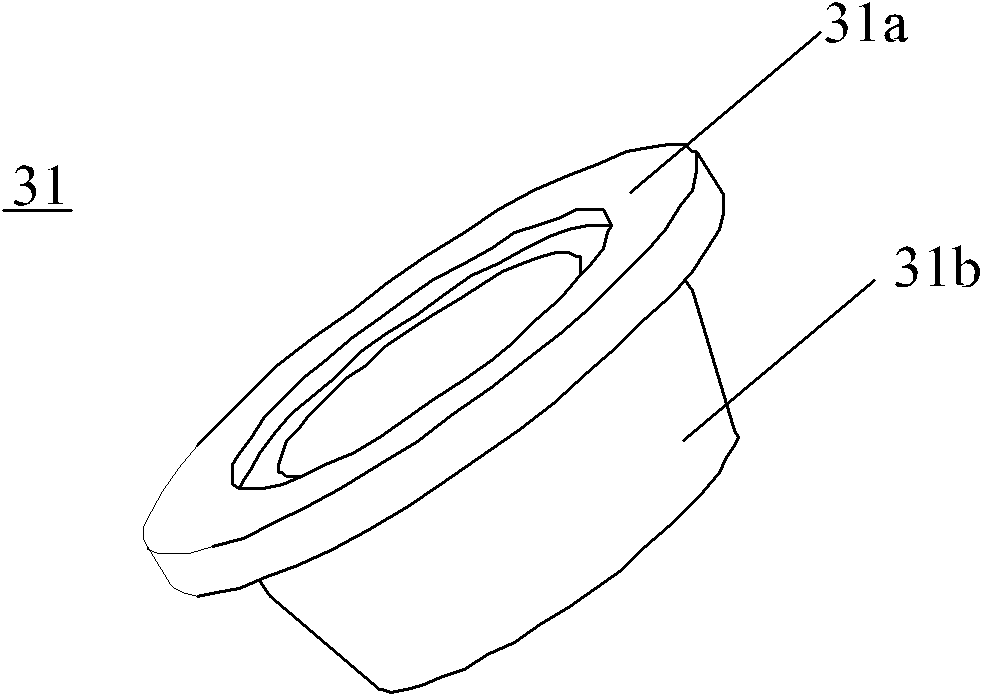
[0015] Such as figure 1 , figure 2 and image 3 As shown, the motor rotor vibration and noise reduction mechanism 100 of the present invention is installed between the end faces of the two bearings 201 of the rotor bracket 200 and a stator (not shown in the figure) to form a motor, including a rotor 1 and a rotating shaft 2. The rotor 1 and the The rotating shaft 2 is sleeved and fixed, the rotating shaft 2 is pivotally connected to the bearing 201 and one end passes through the bearing 201 to form an output shaft, and the motor rotor vibration and noise reduction mechanism 100 also includes a vibration reduction device 3 and The plastic gasket 4, the vibration damping device 3 is respectively arranged symmetrically between the rotor 1 and the end face of the bearing 201, including a retaining ring 31 and a compression spring 32, and the retaining ring 31 has a stepped structure and is socketed The rotating shaft 2 includes a conflicting portion 31a and a socket portion 31b...


PUM


Abstract

The invention discloses a vibration damping and noise reducing mechanism for a motor rotor, which is suitable for small-power or micro-sensing motors. The mechanism comprises a rotor, a rotating shaft and vibration damping devices, wherein the rotor is fixed with the rotating shaft in a sleeve joint mode; the rotating shaft is pivoted on a bearing and one end of the rotating shaft passes through the bearing to form an output shaft; the vibration damping devices are respectively arranged between the rotor and the bearing symmetrically, and comprise a retainer ring and an elastic element; the retainer ring is sleeved on the rotating shaft; the elastic element is sleeved on the rotating shaft; one end of the elastic element is pressed against the retainer ring, and the other end of the elastic element is pressed against the end face of the bearing; and the retainer ring has stair-step structure and comprises a conflict part and a sleeve part, wherein the conflict part is resisted on the rotor, the sleeve part is sleeved on the elastic element. The vibration damping and noise reducing mechanism for the motor rotor can realize vibration damping in the radial direction, and can reduce noise generated by vibration.

Description

technical field [0001] The invention relates to a low-power or miniature induction motor, in particular to a motor rotor vibration reduction and noise reduction mechanism. Background technique [0002] Motor, commonly known as "motor" (transliteration of motor), refers to an electromagnetic device that converts electrical energy into mechanical energy according to the law of electromagnetic induction. It generally includes stator windings, rotors, rotating shafts and brackets, and the stator is fixedly installed on the brackets, and the rotor is installed in the stator and pivotally connected to the brackets. The stator windings are formed by winding wires into coils in a certain way, and the coils are energized. The induced electromotive force acts as a swirl electric field, and then generates torque on the rotor coil to drive the rotor to rotate. [0003] Generally, the rotor of the motor is directly socketed on the rotating shaft, and the rotating shaft is directly pivot...

Claims


Application Information

Patent Timeline
Patent Type & Authority Applications(China)
IPC IPC(8): H02K5/24
Inventor 胡家康陈洪毅
Owner DONGGUAN GUOLIANG MOTOR
Why Eureka
Try Eureka