Cooling system inside variable frequency generator unit

A technology for cooling systems and generator sets, applied in electric components, cooling/ventilation devices, electrical components, etc., can solve the problems of reduced work reliability and life, increased cost, and large volume, avoiding large axial dimensions, The effect of reducing the axial size and compact structure of the unit

Inactive Publication Date: 2011-04-27
SHANGHAI LIGER POWER TECH
View PDF5 Cites 12 Cited by
  • Summary
  • Abstract
  • Description
  • Claims
  • Application Information

AI Technical Summary

Problems solved by technology

At present, the heat dissipation of the inverter controller in the market mainly adopts the following three methods. One is to use a special motor to drive the cooling fan to dissipate heat for the inverter controller. Because of its complex structure, the manufacturing cost is high.
not suitable for mass production
The second is to place the inverter controller at the back end of the air duct, because of the high temperature, which greatly reduces the working reliability and life; the third is to place the inverter controller at the air inlet of the air duct, so that the axial direction of the entire generator set The size is obviously larger, the volume is huge, and the cost is increased. Moreover, this structure makes most of the cooling air not pass through the key heat-generating parts of the inverter controller, but directly enters the subsequent parts for cooling. This method cannot ensure sufficient heat dissipation of the inverter controller, reducing The service life of the inverter controller is shortened, which affects the overall performance of the unit

Method used


Image

  • Cooling system inside variable frequency generator unit
  • Cooling system inside variable frequency generator unit
  • Cooling system inside variable frequency generator unit

Examples


Embodiment Construction

[0016] A preferred embodiment will be given below, and the present invention will be described more clearly and completely in conjunction with the accompanying drawings.

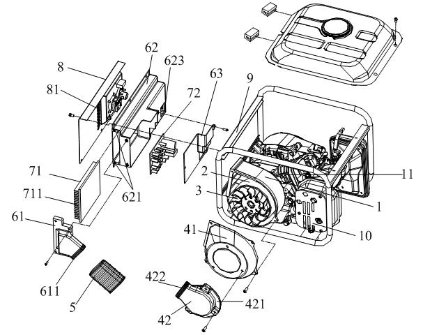
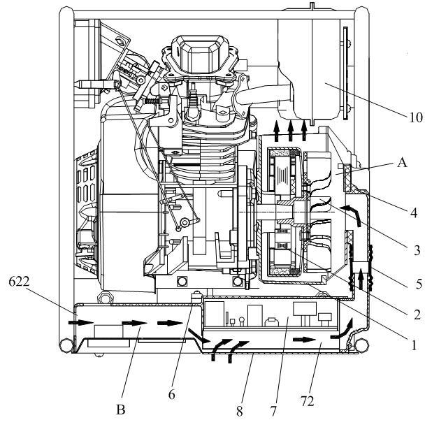
[0017] Such as figure 1 and figure 2 As shown, the cooling system inside the frequency conversion generator set of the present invention mainly includes a generator air guide cover 1, a generator 2, fan blades 3, an air guide cover plate 4, a hose 5, an inverter controller 7, and an inverter air guide Body 6, control panel 8. Wherein, the air guide cover 4 includes an air guide cover 41 and a generator air guide joint 42 . The inverter air guide body 6 includes an inverter air guide slot 62 , an inverter air guide joint 61 and a wind deflector 63 . The generator 2 and the fan blades 3 are inside the generator wind guide cover 1, and together with the wind guide cover plate 4 constitute the generator cooling ventilation folder A; the inverter controller 7 is fixed in the inverter air guide slot on the sid...


PUM


Abstract

The invention discloses a cooling system inside a variable frequency generator unit. The cooling system comprises a generator wind guide cover, a generator, blades, an wind guide cover plate, a hose, an inversion controller, an inverter wind guide body and a control panel, wherein the inverter wind guide body comprises an inverter wind guide groove, an inverter wind guide connector and a wind deflector; the generator and the blades are arranged inside the generator wind guide cover; the inversion controller and the wind guide cover plate form a generator cooling and ventilating intermediate cavity; the inversion controller is fixed inside the inverter wind guide groove which is positioned on one side of the generator; the inversion controller and the control panel form an inverter cooling and ventilating intermediate cavity; and the generator cooling and ventilating intermediate cavity and the inverter cooling and ventilating intermediate cavity are connected by the hose so as to form a cooling air channel. In the cooling system, wind pressure is formed by rotating the blades on the generator so as to ensure that cooling air is forced to pass through a plurality of plate type fins at the back of the inversion controller, then enter the generator cooling and ventilating intermediate cavity through the hose to cool the generator, and finally is discharged from an air outlet of the shell of the generator.

Description

technical field [0001] The invention relates to a frequency conversion generator set, in particular to a cooling system inside the frequency conversion generator set. Background technique [0002] The traditional generator set is inconvenient to carry because of its bulky size, and it is heavy to carry. Therefore, people expect to produce generator sets with light weight, compact structure and high power, so frequency conversion generators have been launched on the market. Because the inverter controller used by this generator widely uses power devices, the operating temperature of these power devices will directly affect the working stability and service life of the entire unit. At present, the heat dissipation of inverter controllers on the market mainly adopts the following three methods. One is to use a dedicated motor to drive a cooling fan to dissipate heat from the inverter controller. Because of its complex structure, the manufacturing cost is high. Not suitable fo...

Claims


Application Information

Patent Timeline
Patent Type & Authority Applications(China)
IPC IPC(8): H02K9/06
Inventor 黄长明夏永胜许付成
Owner SHANGHAI LIGER POWER TECH
Why Eureka
Try Eureka