Method for identifying array element of surface acoustic wave passive wireless array
A surface acoustic wave, passive wireless technology, applied in the direction of electrical components, impedance networks, etc., can solve the problem of not giving full play to the directional characteristics and polarization characteristics of the sensing antenna, and the resonant coding device cannot avoid technical difficulties, and the resonant coding device Complicated structure and other issues, to achieve the effect of reducing the scale of reading and writing equipment, facilitating popularization and application, and good security and stability
- Summary
- Abstract
- Description
- Claims
- Application Information
AI Technical Summary
Problems solved by technology
Method used
Image
Examples
Embodiment 1
[0033]The surface acoustic wave temperature sensor is selected for temperature monitoring of capacitor banks in substations. Most of the equipment failures and abnormalities in the power system are initially accompanied by local or overall overheating or relatively abnormal temperature distribution. The substation is located in the middle link of the power system, and the capacitor is the most monitored point in the substation, and the possibility of problems is relatively large. Once a failure occurs, it will affect the power supply of the entire region, causing huge economic losses and becoming a major Therefore, it is very necessary to monitor the temperature of the capacitor on line in real time. However, the capacitor temperature monitoring points are numerous and densely distributed, and the capacitor itself is in an environment of high voltage, strong magnetic field and extremely strong electromagnetic interference. The harsh on-site environment brings great difficulti...
Embodiment 2
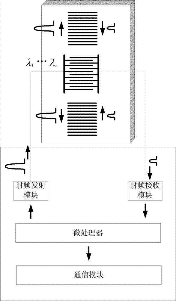
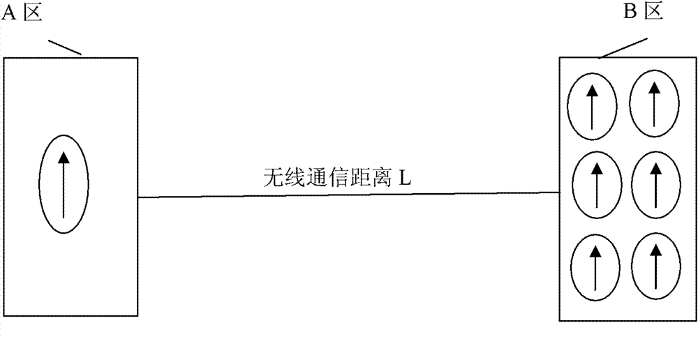
[0035] to combine Figure 4 , this example uses image 3 The 1-to-6 basic multiplexing structure realizes 4-to-24 multiplexing through polarization diversity. Area A is the reader antenna area, which is composed of 4 reader antennas and forms an array in this area through polarization diversity. Area B is the sensor antenna array area, which is composed of 24 antennas, and each 6 antennas is a small diversity group, and the polarization directions of the 4 diversity groups are separated by 45°. The 4 small diversity sets form the polarization diversity set. The polarization direction of each diversity is the same as the polarization direction of the reader-writer antenna it faces.
Embodiment 3
[0037] to combine Figure 5 , this example is the same as image 3 The difference lies in the realization of a larger sensor antenna array through spatial multiplexing on the basis of utilizing polarization diversity. Practical applications Figure 5 The range of the free space in area A shown is relatively large, and the spatial isolation of the reader-writer antenna assembly can be realized to be large. Figure 4 The sensor antenna array in the middle B area is relatively large, making full use of the orientation of the antenna and the spacing between the sensor arrays, and adding spatial spacing isolation on the basis of directional isolation to prevent interference between signals.
PUM
 Abstract
Description
Claims
Application Information
 - R&D
- Intellectual Property
- Life Sciences
- Materials
- Tech Scout
- Unparalleled Data Quality
- Higher Quality Content
- 60% Fewer Hallucinations
Browse by: Latest US Patents, China's latest patents, Technical Efficacy Thesaurus, Application Domain, Technology Topic, Popular Technical Reports.
© 2025 PatSnap. All rights reserved.Legal|Privacy policy|Modern Slavery Act Transparency Statement|Sitemap|About US| Contact US: help@patsnap.com


