
Oblique slip screwdriver operating rod for hand surgery

An operating rod and hand surgery technology, which is applied to the field of inclined-sliding hand surgical screwdriver operating rods, can solve the problems of easy damage of screwdrivers, high cost of surgical instruments, waste, etc., so as to reduce costs, save sterilization space and transportation costs, and avoid waste. Effect

Active Publication Date: 2011-05-04
启东兴源生态有机肥料有限公司
View PDF3 Cites 9 Cited by
  • Summary
  • Abstract
  • Description
  • Claims
  • Application Information

AI Technical Summary

Problems solved by technology

[0002] Most of the existing screwdrivers of different types used in hand surgery are equipped with their own operating rods. Although this design is simple in structure, it is easy to damage the screwdriver and is an inseparable whole with the operating rod. Rods can also be scrapped due to damaged screwdrivers, making surgical instruments cost prohibitive and wasteful
At the same time, since medical instruments need to be sterilized before and after surgery, the operating rod will occupy a large space after entering the disinfection equipment, which increases the cost of disinfection and reduces the efficiency of disinfection.
[0003] To avoid the above problems, it is necessary to make the screwdriver and its operating rod detachable, but it is necessary to achieve a fast connection, quick disassembly and replacement between the two, and a stable, firm, and non-loose connection between the two. In combination, this is a problem that those skilled in the art have been eager to solve but have not been able to thoroughly solve for many years

Method used


Image

  • Oblique slip screwdriver operating rod for hand surgery
  • Oblique slip screwdriver operating rod for hand surgery
  • Oblique slip screwdriver operating rod for hand surgery

Examples


Embodiment Construction

[0018] The present invention will be further described below in conjunction with the accompanying drawings and embodiments.

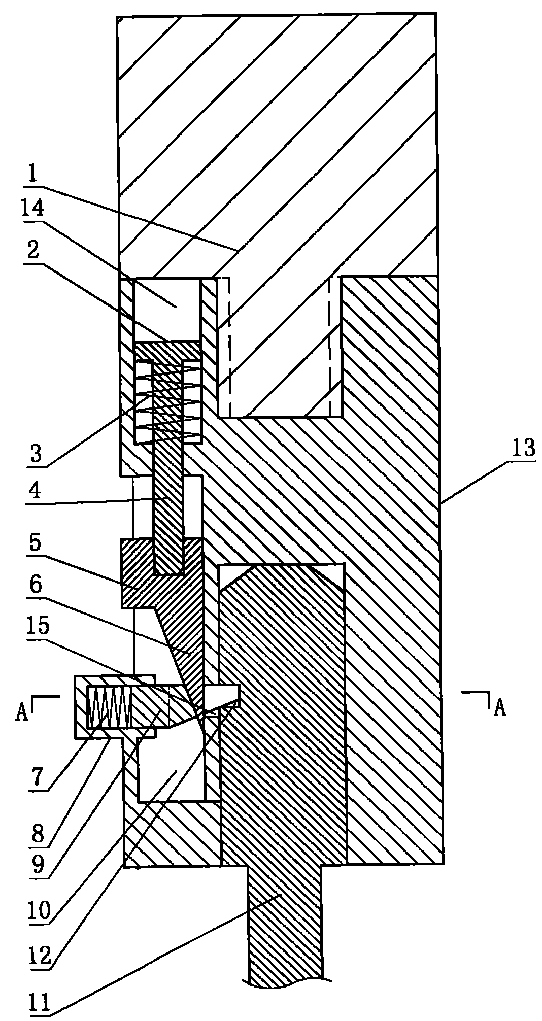
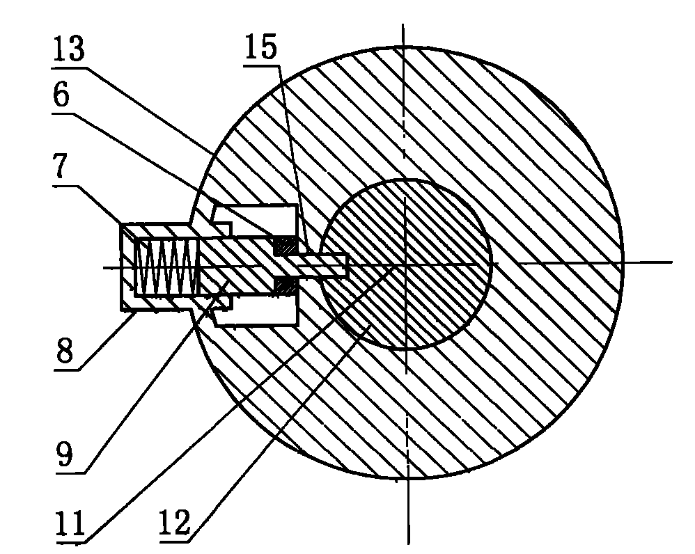
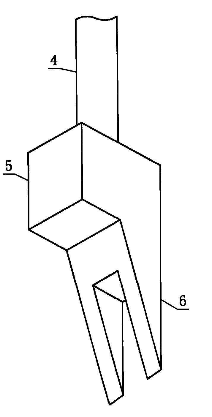
[0019] The operating rod of the inclined-sliding hand surgery screwdriver consists of a handle 1, a fixed spring plate 2, an unlocking spring 3, a moving rod 4, a moving block 5, an oblique fork 6, a locking spring 7, a spring box 8, a locking block 9, an unlocking chamber 10, A replacement head 11, a locking hole 12, an operating rod 13, a spring hole 14 and a through hole 15 are formed.

[0020] The replacement head 11 is composed of a cylindrical rod part, a screwdriver bit and a cylindrical base which are respectively located at two ends of the rod part and are integral with the rod part. A locking hole 12 is formed on the side wall of the base of the replacement head 11 . The upper end of the replacement head 11 base has an annular slope. Both the handle 1 and the operating rod 13 are coaxial cylindrical, and the operating rod 13 is located at th...


PUM


Abstract

The invention relates to a medical device, in particular to an oblique slip screwdriver operating rod for hand surgery. The operating rod is composed of a grab handle, a spring fixing disk, an unlocking spring, a movable lever, a movable block, an oblique fork, a locking spring, a spring case, a locking block, an unlocking cavity, a replacement head, a locking hole, an operating rod and a spring hole, wherein, the bottom end of the operating rod is equipped with a blind hole which is concentric with the operating rod; a base of the replacement head is positioned in the blind hole on the bottom end of the operating rod; the top surface of the operating rod is equipped with the longitudinal spring hole; the unlocking cavity positioned on the side wall of the operating rod is arranged just below the spring hole, and the unlocking cavity is a strip space with a rectangular cross section; the lower end of the spring fixing disk is equipped with the movable lever which is integrated and concentric with the spring fixing disk; the lower end of the movable lever is integrated with the movable block in the unlocking cavity through a circular hole on the bottom of the spring hole; and the lower end of the movable block is equipped with the oblique fork which is integrated with the movable block.

Description

technical field [0001] The invention relates to a medical device, in particular to an oblique and sliding hand surgical screwdriver operating rod. Background technique [0002] Most of the existing screwdrivers of different types used in hand surgery are equipped with their own operating rods. Although this design is simple in structure, it is easy to damage the screwdriver and is an inseparable whole with the operating rod. The rod can also become scrap due to damage to the screwdriver, which makes the surgical instrument cost prohibitive and wasteful. At the same time, since the medical instruments need to be sterilized before and after the operation, the operating rod will occupy a large space after entering the disinfection equipment. On the one hand, the cost of disinfection is increased, and the efficiency of disinfection is also reduced. [0003] To avoid the above problems, it is necessary to make the screwdriver and its operating rod detachable, but it is necessary...

Claims


Application Information

Patent Timeline
IPC IPC(8): A61B17/92
Inventor 何文仙
Owner 启东兴源生态有机肥料有限公司
Learn More