Three-degree-of-freedom program control wire machinery

A program-controlled Weiya machinery and degree of freedom technology, which is applied in entertainment, stage installations, and installations for theaters and circuses, etc., can solve problems such as the restriction of shooting elements, and achieve fast response time, rich shooting elements, and high movement speed. Effect

Active Publication Date: 2011-05-04
FANTAWILD DIGITAL FILM
4 Cites 21 Cited by

AI-Extracted Technical Summary

Problems solved by technology

[0002] Aerial flight performances have been widely used in stage performances, stadium performances, film and television stunt shooting and other fields, commonly known as "Wia" stunts, the current method used is: the mobile car is hung on the main steel cable or guide rail, through the wire rope and pulley block The motor d...

Method used

As shown in Figure 2, in the present embodiment, described foundation column 1 or Y are also provided with limiter 11 to foundation beam 2, and described limiter 11 is provided with bumper 12 and buffer limiter The device 13, the Y-direction basic beam 2 is provided with a sensor rack for detecting displacement and a power-taking trolley line of the whole machine. The limit device 11, the buffer 12 and the buffer limiter 13 can play a role of safety protection and limit when the Y-direction moving car 5 moves out of control, so as to improve safety.
As shown in Figure 3, in the present embodiment, described Y guide rail 3 is double guide rail structure, comprises track, pressing plate 14 and shock absorber 15, and described shock absorber 15 is arranged on track and Y to foundation Between the beams 2, the pressing plate 14 presses the lower end of the track. Described damping pad 15 has damping effect, can reduce the vibration and the noise in Y to sports car 5 running; Double guide rail structure is conducive to the stability of Y to sports car 5 running, increases Y to sports car 5 drive wheels 52. "Rail grabbing" ability prevents the drive wheel 52 of the Y motion car 5 from slipping.
As shown in Figure 4, in the present embodiment, described X crossbeam 4 adopts H-shaped steel to make, and the bottom of described H-shaped steel is guide rail, and promptly surface 1 is as guide rail surface, and the side of H-shaped steel bottom is guide The surface, that is, the surface II is the side as the guide surface, and the surface III of the H-shaped steel is the guide surface and the anti-jump surface. The X-direction crossbeam 4 is used as the carrier of the X-direction moving car 6 and the Z-direction vertical lifting pulley spreader 8, and adopts an i...

Abstract

The invention relates to three-degree-of-freedom program control wire machinery, which comprises a basic upright post, a Y direction basic beam, a Y direction guide rail, an X direction beam, a Y direction moving vehicle, an X direction moving vehicle, an X direction tractor, a Z direction vertical elevating pulley hanger and a Z direction vertical elevating tractor, wherein the Y direction basic beam is arranged on the basic upright post; the Y direction guide rail is arranged on the Y direction basic beam; the Y direction moving vehicle is arranged on a Y direction track; the X direction beam is erected on the Y direction moving vehicle; the X direction moving vehicle is arranged on the X direction beam; the X direction tractor drives the X direction moving vehicle through an X direction hauling rope; the Z direction vertical elevating pulley hanger is arranged on the X direction moving vehicle; and the Z direction vertical elevating tractor is arranged on the X direction beam. The three-degree-of-freedom program control wire machinery can move in the X, Y and Z directions, has the advantages of high moving speed, quick response, thrill of danger and the like and enriches performance and film trick shooting elements.

Application Domain

Technology Topic

Image

  • Three-degree-of-freedom program control wire machinery
  • Three-degree-of-freedom program control wire machinery
  • Three-degree-of-freedom program control wire machinery

Examples

  • Experimental program(1)

Example Embodiment

[0025] In order to describe in detail the technical content, structural features, achieved objectives and effects of the present invention, the following is a detailed description in conjunction with the embodiments and accompanying drawings.
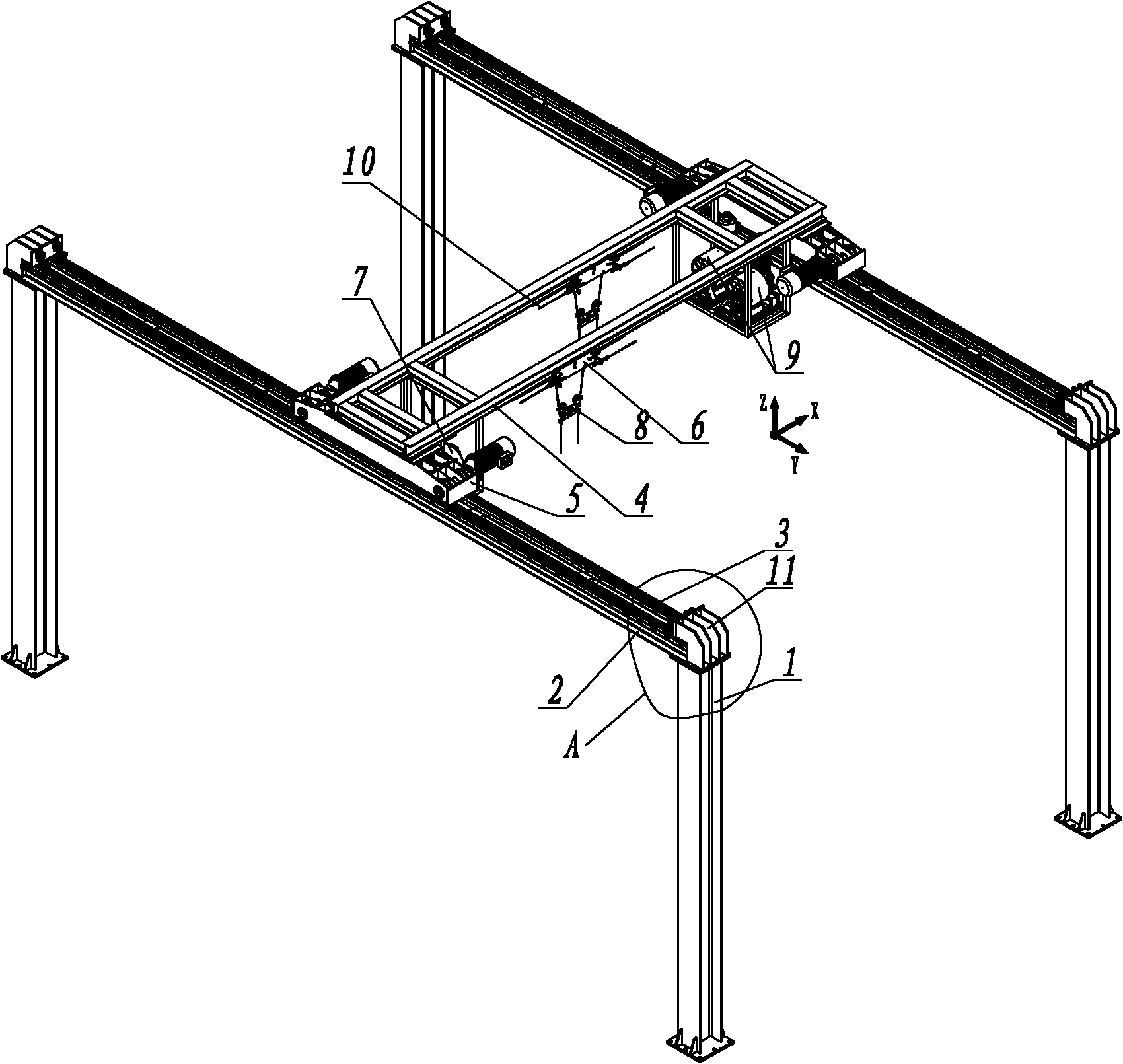
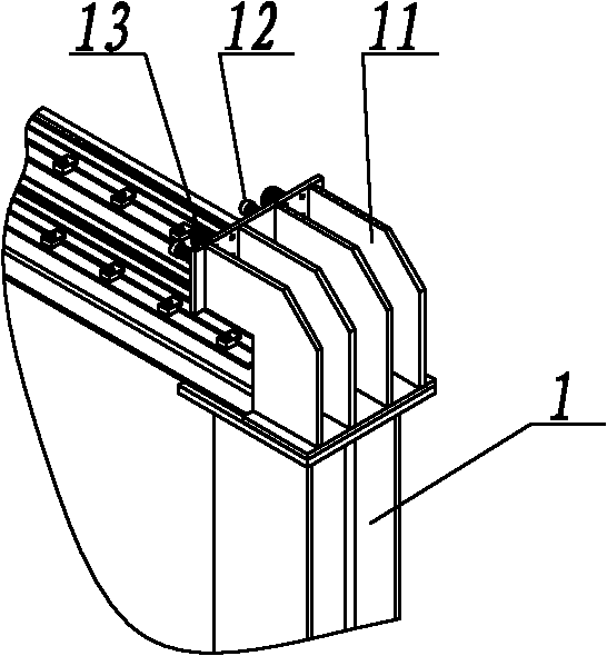
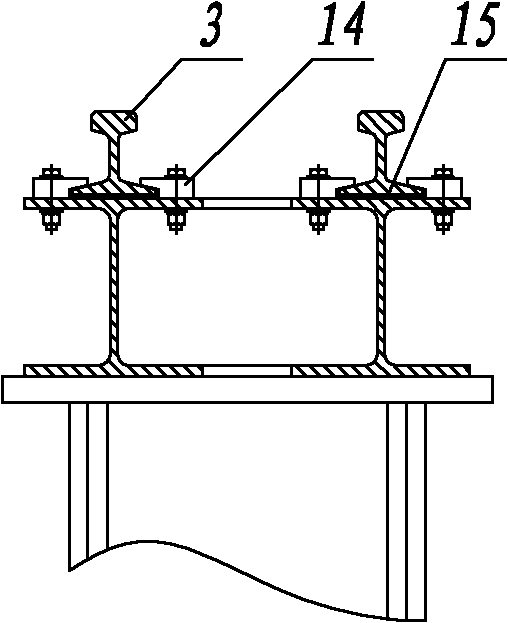
[0026] As an embodiment of the three-degree-of-freedom programmable Wia machine of the present invention, please refer to Figure 1 to Figure 9 , Including foundation column 1, Y-direction foundation beam 2, Y-direction rail 3, X-direction beam 4, Y-direction sports car 5, X-direction sports car 6, X-direction tractor 7, Z-direction vertical lifting pulley spreader 8 and Z Vertical lifting tractor 9, the Y-direction foundation beam 2 is arranged on the foundation column 1, the Y-direction guide rail 3 is arranged on the Y-direction foundation beam 2, and the Y-direction sports car 5 is arranged on the Y-direction rail 3. The X-direction beam 4 is erected on the Y-direction sports car 5, the X-direction sports car 6 is arranged on the X-direction beam 4, and the X-direction tractor 7 drives the X-direction sports car 6 through the X-direction traction rope 10 The Z-direction vertical lifting pulley sling 8 is arranged on the X-direction sports car 6, and the Z-direction vertical lifting tractor 9 is arranged on the X-direction beam 4.
[0027] In this embodiment, the foundation column 1 is the supporting component of the entire program-controlled WIA machine, and its height, distance, and quantity can be set according to the previous planning. The foundation column 1 can be poured with concrete or made of steel structure.
[0028] The Y-direction sports car 5 of the three-degree-of-freedom program-controlled Wia Machinery of the present invention drives the X-direction beam 4 to move on the Y-direction guide 3 to realize the movement in the Y direction; the X-direction tractor 7 drives the X-direction sports car 6 to move on the X-direction beam 4 Move up to realize the movement in the X direction; the Z-direction vertical lifting tractor 9 drives the Z-direction vertical lifting pulley spreader 8 to vertically lift, and realize the movement in the Z direction. Because the three-degree-of-freedom program-controlled WEIA machine of the present invention can move in the three directions of X, Y, and Z, it has three degrees of freedom, and the trajectory of the actor flying in the air is controlled by the program. It has high movement speed, fast response time, thrilling excitement, etc. Advantages, thereby enriching the performance and film and television stunt shooting elements.
[0029] Such as image 3 As shown, in this embodiment, the Y-direction guide rail 3 is a double-rail structure, including a rail, a pressure plate 14 and a shock-absorbing pad 15. The shock-absorbing pad 15 is arranged between the rail and the Y-direction foundation beam 2, so The pressing plate 14 presses the lower end of the rail. The shock-absorbing pad 15 has a shock-absorbing effect, which can reduce the vibration and noise during the operation of the Y-direction sports car 5; the dual-rail structure is conducive to the smoothness of the Y-direction sports car 5 and increases the driving wheels 52 of the Y-direction sports car 5 The "rail grasping" capability prevents the driving wheels 52 of the Y-direction sports car 5 from slipping.
[0030] Such as figure 2 As shown, in this embodiment, the base column 1 or the Y-direction foundation beam 2 is further provided with a limit device 11, and the limit device 11 is provided with a buffer 12 and a buffer limiter 13, and the Y The basic beam 2 is provided with a sensor rack for detecting displacement and a sliding contact line for the entire machine. The limit device 11, the buffer 12 and the buffer limiter 13 can play a role of safety protection and limit when the Y-direction sports car 5 is out of control, and improve safety.
[0031] Such as Figure 4 As shown, in this embodiment, the X-direction beam 4 is made of H-shaped steel, the lower side of the H-shaped steel is a guide rail, that is, the surface I is the guide surface, and the side surface under the H-shaped steel is the guide surface, that is, the surface II is The side is the guiding surface, and the surface III of the H-shaped steel is the guiding surface and the anti-bounce surface. The X-direction beam 4 is used as the bearing body of the X-direction sports car 6 and the Z-direction vertical lifting pulley spreader 8. It adopts an integrated design and does not need to lay additional guide rails, which reduces the structural weight and simplifies the production and installation process.
[0032] Such as Figure 7 As shown, in this embodiment, the X-direction sports car 6 includes a frame 61, main wheels 62, side guide wheels 63, anti-bounce wheels 64, a traction rod 65 and a fixed pulley 66, the traction rod 65 and the fixed pulley The pulleys 66 are all arranged on the frame 61, the Z-direction lifting traction rope 82 is arranged on the fixed pulley 66, the X-direction traction rope 10 is fixed on the traction rod 65, and the traction rod 65 is also provided with a traction rope Tensioning device.
[0033] Such as Figure 5 As shown, in this embodiment, the Y-direction sports car 5 includes a frame 51, a drive wheel 52, a motor 53, and a drive shaft 54. The drive wheel 52 is arranged on the drive shaft 54 ​​and the motor 53 drives the vehicle. Said drive shaft 54, each Y-direction sports car 5 uses two motors 53, and each motor 53 drives one or a group of drive wheels 52 respectively. The drive wheels 52 are placed on the working surface of the Y-direction rail 3 and have power. The advantages of uniform distribution, anti-skid, etc., the motor 53 is a dual-brake motor, and a rotary encoder for collecting control data is installed in the motor 53.
[0034] Such as Image 6 As shown, in this embodiment, the Z-direction vertical lifting pulley spreader 8 includes a hanger 81, a Z-direction lifting traction rope 82, a movable pulley 83 and an actor sling 84. The movable pulley 83 is arranged on the hanger 81, The Z-direction lifting traction rope 82 is hung on the movable pulley 83, one end of the Z-direction lifting traction rope 82 is fixed, and the other end is connected with the Z-direction vertical lifting traction machine 9, and the actor sling 84 is also set on the hanger 81. The actor sling 84 is connected to the performer and moves together with the Y-direction sports car 5 and the X-direction sports car 6. At the same time, the Z-direction vertical lifting pulley spreader 8 is driven by the Z-direction vertical lifting tractor 9, due to the action of the moving pulley 83 , The instantaneous displacement of the vertical lifting movement in the Z direction will not be changed by the movement of the X-direction sports car 6.
[0035] Such as Picture 9 As shown, in this embodiment, the X-direction traction machine 7 includes a bracket 71, a motor 72, a reel 73, and a stroke limiter 74. The motor 72 is a dual-brake motor, and the motor is equipped to collect control data. In the rotary encoder, the stroke limiter 74 can play a role in detecting the limit position.
[0036] In this embodiment, the Z-direction vertical lifting tractor 9 includes a bracket, a motor, a reel, and a stroke limiter. The motor is a dual-brake motor. The motor is equipped with a rotary encoder for collecting control data. The stroke limiter can play a role in detecting the limit position.
[0037] The above are only the embodiments of the present invention, and do not limit the scope of the present invention. Any equivalent structure or equivalent process transformation made by using the content of the description and drawings of the present invention, or directly or indirectly applied to other related technologies In the same way, all fields are included in the scope of patent protection of the present invention.

PUM

no PUM

Description & Claims & Application Information

We can also present the details of the Description, Claims and Application information to help users get a comprehensive understanding of the technical details of the patent, such as background art, summary of invention, brief description of drawings, description of embodiments, and other original content. On the other hand, users can also determine the specific scope of protection of the technology through the list of claims; as well as understand the changes in the life cycle of the technology with the presentation of the patent timeline. Login to view more.

Similar technology patents

Optical modulator

ActiveCN111240048AEfficient modulationFast movementNon-linear opticsElectrically conductiveIr microscope
Owner:GUIZHOU MINZU UNIV

Transportation cabin for packaging pressure testing and emptying equipment

Owner:PETRO OIL & LUBRICANT RES INST OF THE GENERAL LOGISITIC DEPT OF PLA

Classification and recommendation of technical efficacy words

  • Fast movement
  • Short response time

Electrowetting devices

Owner:IMPERIAL INNOVATIONS LTD +1
Why Eureka
Try Eureka