Yarn winding device

A technology for winding machines and yarns, applied in the field of yarn winding machines, can solve the problems of breakage, easy contact with push-out parts, and reduced package quality, and achieve the effects of preventing breakage, preventing interference, and preventing quality reduction.

Active Publication Date: 2011-05-04
TMT MACHINERY INC
View PDF5 Cites 2 Cited by
  • Summary
  • Abstract
  • Description
  • Claims
  • Application Information

AI Technical Summary

Problems solved by technology

In addition, there is a possibility that the ejection part or the contact position of the bobbin holder may be worn and damaged
In addition, the yarn wound on the bobbin pushed out by the push-out member tends to come into contact with the push-out member near the open end of the bobbin holder, which may result in lower package quality.

Method used


Image

  • Yarn winding device
  • Yarn winding device
  • Yarn winding device

Examples


Embodiment Construction

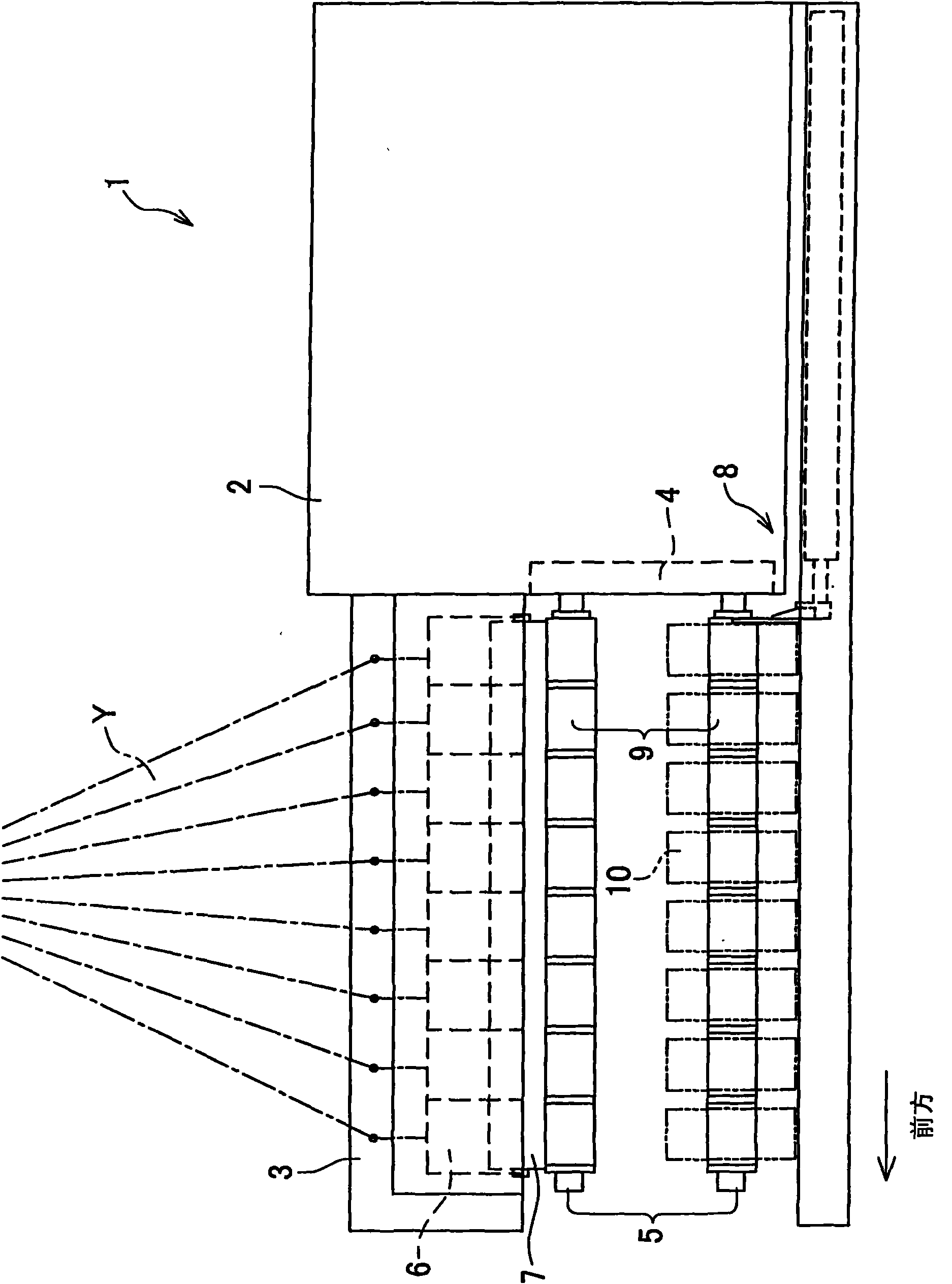
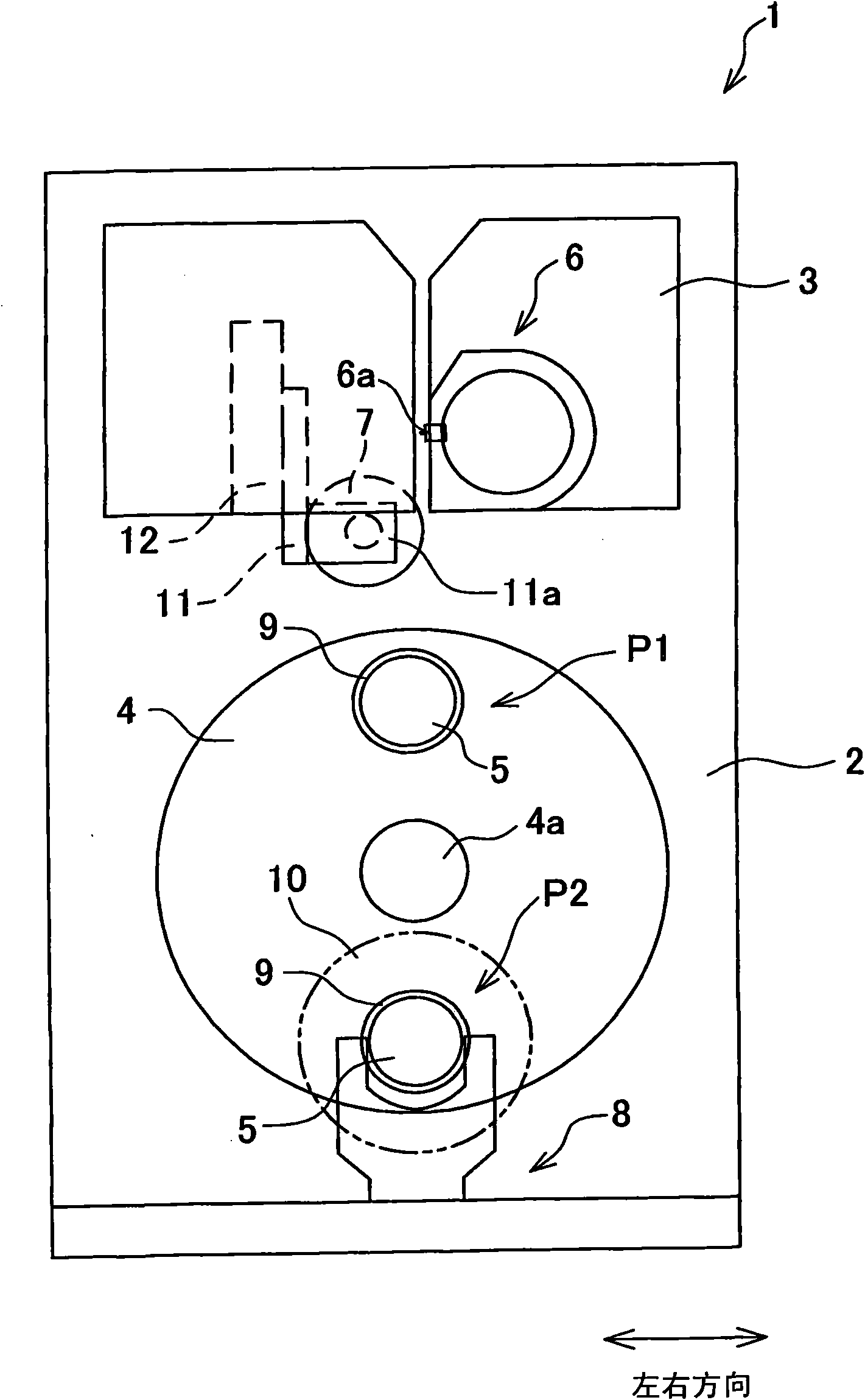
[0019] Next, embodiments of the present invention will be described. figure 1 It is a side view of the yarn winding machine according to one embodiment of the present invention. figure 2 It is the front view of the yarn winding machine. Such as figure 1 As shown, a plurality of yarns Y are continuously supplied to the yarn winding machine 1 from a spinning machine (not shown). In addition, the yarn winding machine 1 is configured to wind a plurality of yarns Y supplied from a spinning machine on a plurality of bobbins 9 to form a plurality of packages 10, and the plurality of packages 10 are removed by the pusher 8. .

[0020] Such as figure 1 and figure 2 As shown, the yarn winding machine 1 includes a main body support 2, an elevating frame 3 provided on the main body support 2 so as to be movable (up and down) in the vertical direction, and a disc-shaped turntable rotatably provided on the main body support 2. 4. One end is supported by the turntable 4 and is equipp...


PUM


Abstract

The present invention provides a yarn winding device which detaches a plurality of packages from a bobbin bracket when the damage of a pushing-out member and the bobbin bracket and package quality reduction are prevented. The yarn winding device supports one end of each of two shaft-shaped bobbin brackets (5) which respectively have a larger length in one direction on a turntable (4). Each bobbin bracket (5) is provided with a plurality of bobbins (9). A turntable (4) switches the position of a bobbin bracket between a winding position (P1) and a standby position (P2). The yarn winding device moves a pushing-out plate (21) from a base end of the bobbin bracket (5) to an open ed. The pushing-out plate (21) contacts with a left end and a right end of an end face of a bobbin (9) which is most adjacent with a package (10) at the side of the turntable (4) on the bobbin bracket (5) at a standby position (P2), and pushes out the package (10) frontward for detaching a plurality of packages (10). The pushing-out plate (21) can retreat to a position which is separate from a motion area of the bobbin bracket that moves along with the rotation of the turntable (4).

Description

technical field [0001] The present invention relates to a yarn winding machine for simultaneously winding yarn onto a plurality of bobbins mounted on one bobbin holder. Background technique [0002] Conventionally, a known yarn winding machine winds a plurality of bobbins continuously supplied from a spinning machine or the like on a plurality of bobbins installed in series in the axial direction of a shaft-shaped bobbin holder that is long in one direction. . This kind of yarn winding machine has such a structure: it has two bobbin supports with one end rotatably supported on the turntable. Switch between the lower winding position and the standby position for bobbin exchange. [0003] The yarn winding machine rotates a bobbin holder at a winding position, and winds yarn onto a plurality of bobbins mounted on the bobbin holder to form a plurality of packages. Then, the turntable is rotated to move the bobbin holder on which the plurality of packages are mounted to the st...

Claims


Application Information

Patent Timeline
IPC IPC(8): B65H67/052
CPCB65H67/048B65H67/0411B65H2701/31
Inventor 泽田淳
Owner TMT MACHINERY INC
Why Eureka
Try Eureka