Rope-free lifting machine using lifting force as brake drive force

A technology for brakes and hoists, applied in elevators, elevators in buildings, transportation and packaging, etc., can solve the problems of difficulty in realization, large lifting load and large volume, and achieve the effect of preventing flying accidents and ensuring safety.

Inactive Publication Date: 2011-05-04
HENAN POLYTECHNIC UNIV
View PDF3 Cites 12 Cited by
  • Summary
  • Abstract
  • Description
  • Claims
  • Application Information

AI Technical Summary

Problems solved by technology

There are the following problems: On the one hand, the brake requires a dedicated power supply or power, and on the other hand, a dedicated brake controller is required
Finally, because the linear motor cordless hoist has no counterweight and the lifting load is large, the brake drive power is large, the vol...

Method used


Image

  • Rope-free lifting machine using lifting force as brake drive force
  • Rope-free lifting machine using lifting force as brake drive force
  • Rope-free lifting machine using lifting force as brake drive force

Examples


Embodiment 1

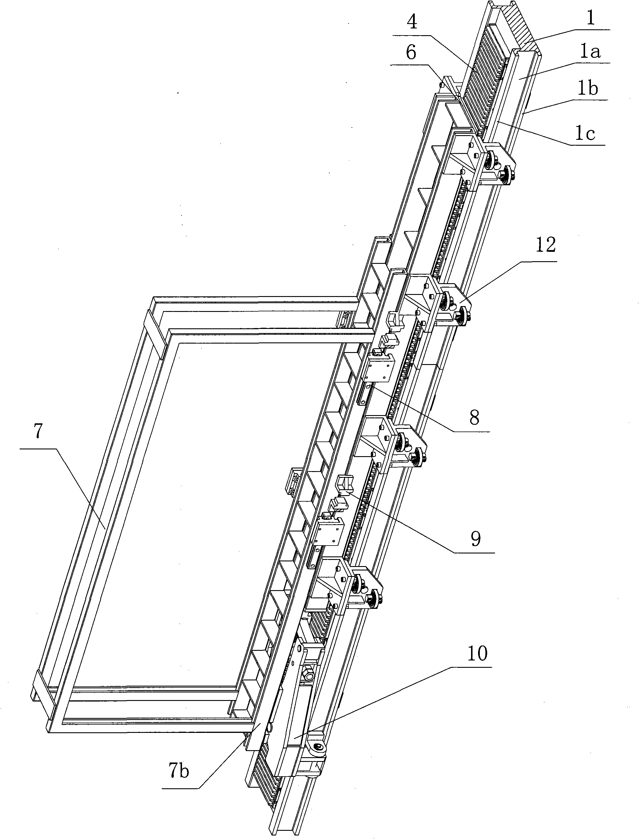
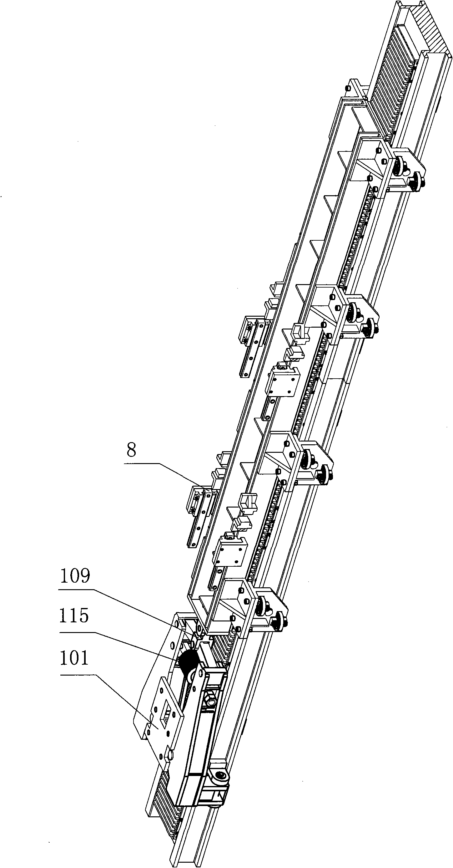
[0037] Such as figure 1 , figure 2 , image 3 As shown, the cordless hoist using the lifting force as the brake driving force of the present invention mainly includes a supporting steel beam assembly, a car, a linear motor driving device, a positioning guide device, and a braking device.

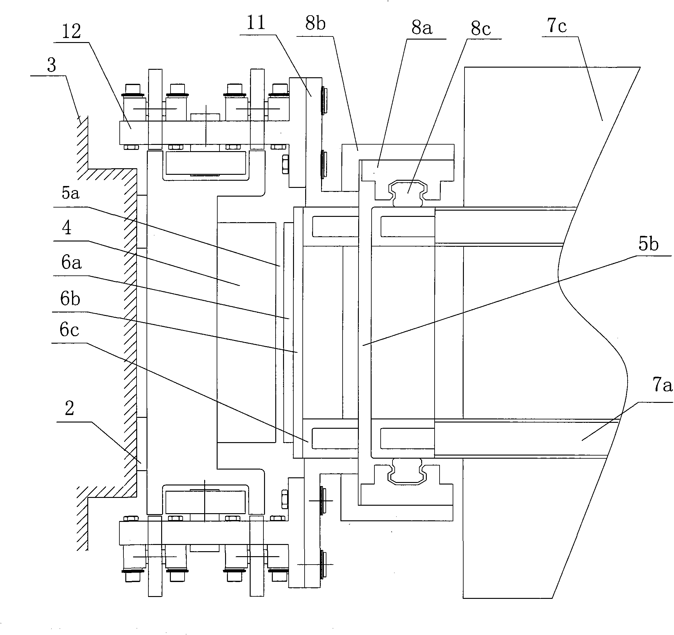
[0038] The supporting steel beam assembly 1 is a long strip and is installed on the mounting support 2 on the inner wall of the wellbore along the vertical direction. The linear motor stator 4 of the linear motor driving device is installed on the front of the supporting steel beam assembly 1. A concave strip groove 1a with an opening facing outward is provided along the vertical direction;

[0039] On both sides of the concave strip groove 1a are convex bars I 1b and convex bars II 1c, and the convex bars I 1b or convex bars II 1c are used as the brake rails of the safety gear protection device;

[0040] The concave strip groove 1a contains the brake block 103 of the booster caliper brake 10. Whe...

Embodiment 2

[0084] The base of the booster caliper brake (5) is installed on the linear motor mover (6), the brake push rod (109) is hinged or solidified with the car frame back plate (7b), and the brake block (103) ) Acting on the bottom surface (1d) of the concave strip groove supporting the steel beam assembly (1). Others are the same as in Example 1.

Embodiment 3

[0086] The positioning and guiding device of the linear motor mover 6 of the present invention can also be realized by linear guide rails and sliders. The linear guide rails are installed on the two sides of the supporting steel beam assembly 1, and the sliders are installed on the back of the linear motor mover. The iron 6b corresponds to the side surface and is aligned with the linear guide rail. The slider can slide freely on the linear guide rail to ensure that the linear motor mover 6 moves up and down in the vertical direction on the supporting steel beam assembly 1. Others are the same as in Example 1.


PUM


Abstract

The invention discloses a rope-free lifting machine using a lifting force as a brake drive force. The rope-free lifting machine comprises a supporting girder assembly, a cage, a linear electric motor drive device, a location guiding device, a brake device, a pair of safety tongs and a bumper. Concave strip grooves used as braking rails of the brake device and guiding rails of guiding location wheels are arranged on two side surfaces of the supporting girder assembly. A rotor of a linear electric motor is in split sliding connection with the cage and is connected with a brake push rod, the lifting force of the rotor of the linear electric motor is used as the brake releasing force of a boost type clamp brake, the down accelerated speed of the rope-free lifting machine can be automatically limited without using a special brake drive power supply, a brake driver and a controller, thus the structure of the brake is simplified. The rope-free lifting machine has the four defensive functionsof the power-off protection of the brake, the safety speed-limiting of the brake, the power-off dynamicbraking of the linear electric motor and the overspeed brake of the safety tongs, and fundamentally ensures the safety and the reliability of the lifting machine.

Description

Technical field [0001] The invention belongs to the field of cordless hoisting, and in particular relates to a cordless hoist using a lifting force as the driving force of a brake. Background technique [0002] The hoist or elevator is an important transportation link in mines and various buildings. In ordinary hoisting systems, the hoisting method is well-known. The structure of the hoist is that the machine room is installed on the upper part of the hoist. The rotating motor drives the drum and winds. One end of the steel wire rope on the drum is connected to the car, and the other end is connected to a counterweight. For ultra-high buildings and ultra-deep mines with a large number of people and heavy loads, a high level of transportation and handling capacity is required. However, the hoist occupies a large amount of building space and low transportation capacity is a serious problem. [0003] In order to overcome the above-mentioned problems, a linear motor cordless hoist tha...

Claims


Application Information

Patent Timeline
IPC IPC(8): B66B9/02B66B7/02B66B11/00B66B5/16
Inventor 汪旭东许孝卓许宝玉封海潮袁世鹰
Owner HENAN POLYTECHNIC UNIV
Why Eureka
Try Eureka