Digital generator device

A digital generator and engine technology, applied in engine components, machines/engines, engine cooling, etc., can solve the problems of unbalanced temperature of the whole machine, reduce heat generation, high cost, etc., to improve overall performance and reliability, The effect of lowering the overall temperature and lowering the production cost

Active Publication Date: 2012-10-17
CHONGQING LIHUA AUTOMATION TECH CO LTD
View PDF0 Cites 0 Cited by
  • Summary
  • Abstract
  • Description
  • Claims
  • Application Information

AI Technical Summary

Problems solved by technology

This structure can produce a good cooling effect on the inverter, generator, and engine, but because only the residual wind reaches the muffler, it can only cool the part of the muffler, so the cooling effect on the muffler is very poor
The muffler is a component with relatively large heat generation. After the muffler is overheated, the local temperature of the entire digital generator is too high, which leads to an imbalance in the temperature of the whole machine, which in turn affects the performance of the whole machine and greatly reduces the output power of the engine.
In order to prevent the engine output power from dropping sharply and the local temperature of the generator from being too high, only the power of the generator can be reduced to reduce the calorific value, which restricts the improvement of the performance of the generator
[0005] Simultaneously, the digital generator of above-mentioned this existing structure, compares with traditional common small-sized generator, cancels engine flywheel, so whole structure can be relatively smaller, but because canceled flywheel, causes each component size and traditional Compared with ordinary small generators, there are changes, so each component in the generator, engine and other components needs to be molded separately. If the manufacturer of traditional ordinary small generators wants to produce digital Generators, there is a problem of excessive cost

Method used


Image

  • Digital generator device
  • Digital generator device
  • Digital generator device

Examples


Embodiment Construction

[0017] The present invention will be described in further detail below in conjunction with the accompanying drawings and specific embodiments.

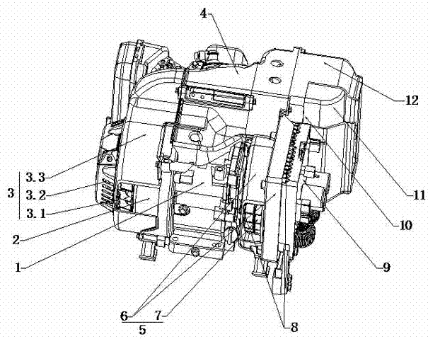
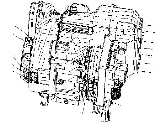
[0018] like figure 1 , 2 As shown, a digital generator device includes: an engine 1 with a shock absorbing device and a generator 2 coaxially arranged with the engine crankshaft and driven by the engine (from the direction shown in the figure, the engine 1 is located in the entire The middle part of the device, the generator 2 is located on the left side of the engine 1); the inverter 9 on the side of the cooling fan 5 on the right side of the engine 1 (as seen from the figure, the inverter 9 is arranged on the far right of the entire device), The inverter 9 corresponds to the air inlet 8 of the cooling fan 5; the rotor of the generator 2 is provided with an impeller 3.1 coaxial with the crankshaft of the engine 1, and a windshield 3.3, which is provided with an air inlet 3.2, Simultaneously at the outlet position of wind cover 3.3,...


PUM


Abstract

The invention discloses a digital generator device. The digital generator device comprises an engine with a damping device, a generator connected with one end of an engine crankshaft, a cooling system belonging to the engine, a cooling fan arranged on the other side of the engine case body, an inverter arranged on an external fixing support frame and a muffler connected with the exhaust pipe of the engine, wherein the impeller of the cooling fan is connected with the other end of the engine crankshaft, the outside of the cooling fan is provided with a volute, one side of the volute, adjacent to the engine and another side adjacent to the inverter are separately provided with air inlets, one side of the volute, adjacent to the muffler is provided with an air outlet; the inverter corresponds to the air inlet of the cooling fan and is arranged on one side of the muffler; and the air inlet and air outlet on the side edge of the volute form a new cooling air duct, thus the temperature of the muffler can be obviously reduced and the bulk temperature of the digital generator device can be reduced. Therefore, the power generation power of the digital generator can be designed to be higherand the overall performance of the digital generator device can be increased.

Description

technical field [0001] The invention relates to the field of small generators, in particular to a digital generator. Background technique [0002] A digital generator is a small generator that generates electrical energy through the synchronous operation of the generator driven by the engine, and then processes the output electrical energy through the inverter to make the frequency, waveform, voltage and other performances of the small generator very high. Compared with ordinary small generators, the volume is smaller, the performance is more reliable, and the power supply quality is higher; in addition, the speed of the engine changes in time with the change of the load, so that the fuel consumption of the engine is lower than the rated load. Smaller, so as to achieve the purpose of energy saving. [0003] Most of the existing digital generator sets have only one cooling fan, and there are many heat-generating components in the unit, such as engines, generators, inverters ...

Claims


Application Information

Patent Timeline
Patent Type & Authority Patents(China)
IPC IPC(8): F01P5/02F01P1/06F02B63/04
Inventor 何林周国兵
Owner CHONGQING LIHUA AUTOMATION TECH CO LTD
Why Eureka
Try Eureka