Piston lubricating system for concrete cylinder

A concrete cylinder and piston lubrication technology, which is applied to the lubrication of engines, piston pumps, lubricating parts, etc., can solve problems such as waste of lubricating oil, poor lubrication effect, inconsistent response time, etc.

Active Publication Date: 2011-05-04
ZOOMLION HEAVY IND CO LTD
View PDF8 Cites 20 Cited by
  • Summary
  • Abstract
  • Description
  • Claims
  • Application Information

AI Technical Summary

Problems solved by technology

However, since the actions of the piston rod 6' and the lubricating oil distributor 7' both require response time, the response time of the two is not consistent; and under different working conditions, the change of hydraulic oil pressure and flow will cause the piston rod to The reversing time of 6' and the oil injection time of lubricating oil distributor 7' change; in addition, the stroke of piston rod 6' also changes with the pressure and flow of hydraulic oil, and sometimes it cannot even reach the end of its stroke
The above reasons will cause the lubricating oil to not be accurately applied to the concrete piston 5', resulting in poor lubricating effect and waste of lubricating oil

Method used


Image

  • Piston lubricating system for concrete cylinder
  • Piston lubricating system for concrete cylinder
  • Piston lubricating system for concrete cylinder

Examples


Embodiment Construction

[0028] Specific embodiments of the present invention will be described in detail below in conjunction with the accompanying drawings. It should be understood that the specific embodiments described here are only used to illustrate and explain the present invention, and are not intended to limit the present invention.

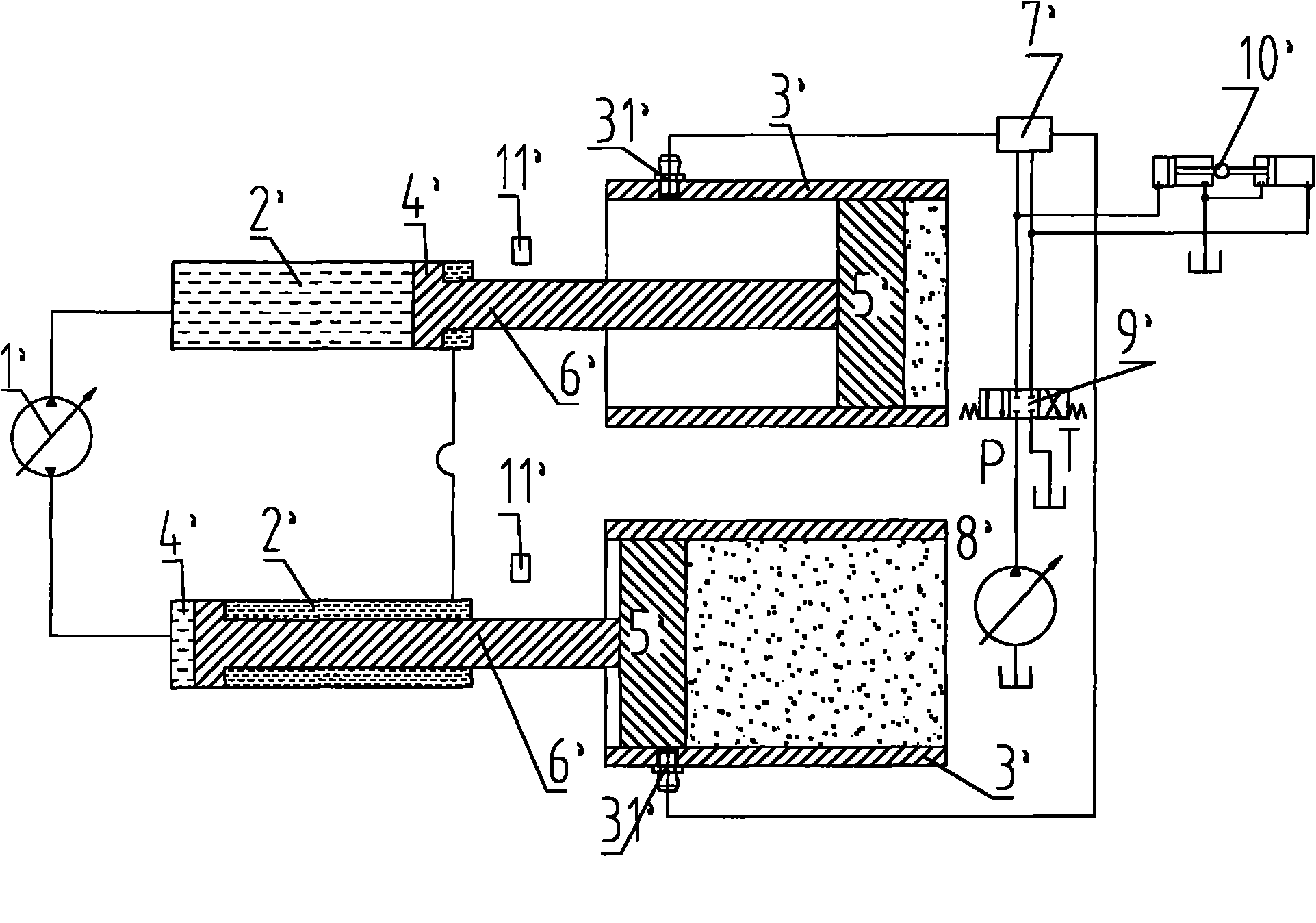
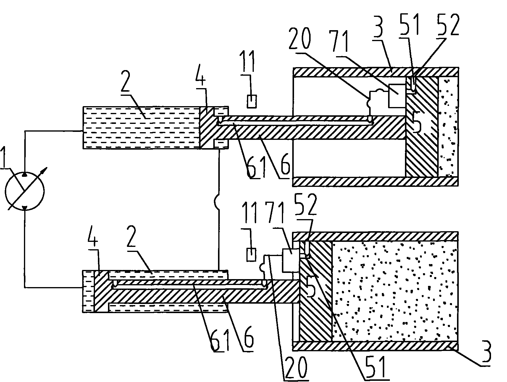
[0029] Such as Figure 2 to Figure 5 As shown, the present invention provides a piston lubrication system for a concrete cylinder, the lubrication system includes a hydraulic pump 1, a main cylinder 2, a concrete cylinder 3, a cylinder piston 4 located in the main cylinder 2, a cylinder piston 4 located in the concrete cylinder 3 The concrete piston 5 and the piston rod 6 inside, the cylinder piston 4 is connected with the concrete piston 5 through the piston rod 6, one of the rod cavity and the rodless cavity of the master cylinder 2 (such as figure 2 and Figure 4 Shown is a rodless chamber) connected to the hydraulic pump 1, wherein the lubrication system ...


PUM


Abstract

The invention discloses a piston lubricating system for concrete cylinders, comprising a hydraulic pump (1), main oil cylinders (2), concrete cylinders (3), oil cylinder pistons (4) positioned in the main oil cylinders, concrete pistons (5) positioned in the concrete cylinders, piston rods (6), and a hydraulic lubricating device. Piston rod channels (61) are formed on the piston rods, lubricatingchannels (51) are formed on the concrete pistons, the oil inlet ends of the piston rod channels are communicated with a cavity with piston rod or a cavity without piston rod of the main oil cylinders, the oil outlet ends of the piston rod channels are communicated with the oil inlets of the hydraulic lubricating device, the oil outlets of the hydraulic lubricating device are communicated with theoil inlet ends of the lubricating channels, the oil outlets of the lubricating channels are communicated with the lubricating holes (52) formed in the circumferential walls of the concrete pistons. The lubricating system can accurately apply lubricating oil on the pistons of the concrete cylinders, so that lubrication effect is good and the waste of the lubricating oil is reduced.

Description

technical field [0001] The invention relates to a piston lubricating system, in particular to a concrete cylinder piston lubricating system. Background technique [0002] Concrete pumps and concrete pump trucks are widely used in the concrete delivery of large-scale concrete projects such as high-rise buildings, expressways, and overpasses. The concrete is mainly delivered by making the concrete piston reciprocate in the concrete cylinder. [0003] The lubrication methods of the piston (ie, "concrete piston") of the concrete cylinder (ie, "concrete delivery cylinder") are basically divided into manual lubrication and automatic lubrication. Manual lubrication refers to setting a lubrication point on the concrete cylinder or concrete piston, and manually injecting oil or spraying lubricating oil on the concrete cylinder or concrete piston. Manual lubrication is labor-intensive, and the lubricating oil is applied unevenly. If the lubrication is not performed in time, it will c...

Claims


Application Information

Patent Timeline
Patent Type & Authority Applications(China)
IPC IPC(8): F04B53/18
CPCF16N7/385F01M2001/083F04B9/107F04B15/02F04B53/18F16N27/02
Inventor 李沛林
Owner ZOOMLION HEAVY IND CO LTD
Why Eureka
Try Eureka