Supercharge Your Innovation With Domain-Expert AI Agents!

Reconstruction of 3d image datasets from X-ray cone-beam data

A technology of three-dimensional image and cone beam, which is applied in image data processing, generation of 2D image, reconstruction according to projection, etc., and can solve problems such as no cone beam projection reconstruction algorithm

Inactive Publication Date: 2011-05-04
SIEMENS AG
View PDF2 Cites 10 Cited by
  • Summary
  • Abstract
  • Description
  • Claims
  • Application Information

AI Technical Summary

Problems solved by technology

However, these systems have not been used to reconstruct 3D images because in such X-ray systems, the X-ray source will move along a planar polygon-based trajectory during one 3D scan
Unfortunately, there are no available reconstruction algorithms for cone beam projections obtained with non-circular trajectories

Method used


Image

  • Reconstruction of 3d image datasets from X-ray cone-beam data
  • Reconstruction of 3d image datasets from X-ray cone-beam data
  • Reconstruction of 3d image datasets from X-ray cone-beam data

Examples


Embodiment Construction

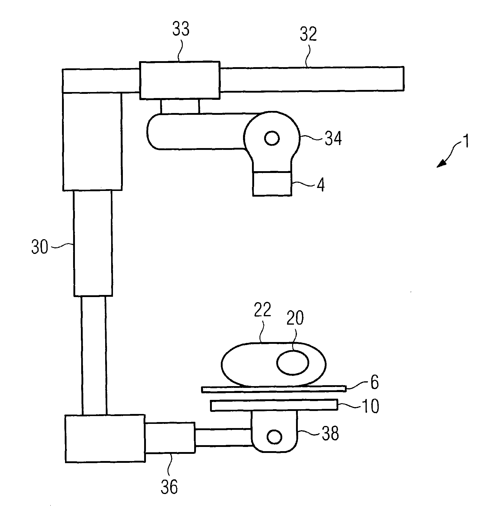
[0073] figure 1 is a schematic diagram of an imaging system on which the invention can be implemented. The patient 22 can be placed on the patient couch 6 . The object to be imaged may be an area 20 inside the patient. The X-ray source 4 is mounted so that translational movement in several directions is possible by means of a telescopic arm 30 and a track 32 along which the X-ray source can slide at a slider 33 . Furthermore, the X-ray source is mounted on the junction 34 so that it can be tilted so that the cone beam of radiation it emits will pass through the object 20 and then hit the detector 10 .

[0074] The detector 10 is preferably a flat panel detector and is itself mounted tiltably via the joint 38 . The joint 38 is translationally movable on the telescoping arm 36 .

[0075] It should be noted that numerous variations are possible with respect to the construction of the imaging system, in particular with regard to the mounting of the X-ray source 4 and the dete...


PUM


Abstract

The invention is directed to a method for producing a 3D image dataset of an object (20) with an imaging system (1) having an X-ray source (4) for emitting photon rays in a cone beam and a detector (10) comprising a two-dimensional array of detector elements adapted for receiving photons emitted by the X-ray source, the method comprising: acquiring (100) a series of two-dimensional arrays of cone beam data from the detector (10) while the source (4) moves along a substantially planar trajectory (40) around the object to be imaged, the trajectory being described by a series of source points serially numbered by a counter parameter; and reconstructing a 3D image from the cone beam data by performing the following steps: A) differentiating the cone beam data with respect to the counter parameter (Lambada) of the source trajectory at fixed ray direction (Alpha) to produce a derivative of the cone beam data; B) filtering the derivative with a Hilbert-like filter to produce filtered cone beam data; C) either before step A), or after step B) multiplying the acquired cone beam data or the filtered cone beam data, respectively, with a redundancy weighting function; and D) back-projecting the cone beam data to compute a 3D image dataset.

Description

technical field [0001] The present invention generally relates to a method and imaging system capable of generating a three-dimensional (3D) image data set of an object. The imaging system includes an X-ray source that emits X-rays in a cone-shaped beam (commonly called a cone-beam) and includes a detector for acquiring a projected image of an object at a time (commonly called a cone-beam projection). A detector of a two-dimensional (2D) array of elements. More specifically, the present invention relates to a new method for reconstructing a three-dimensional image data set from cone beam data acquired by such an imaging system. Background technique [0002] In a fan beam computed tomography (CT) system, an X-ray source projects a fan beam that is collimated to lie within the xy plane of a Cartesian coordinate system called the imaging plane. A beam of X-rays passes through an object being imaged (such as a medical patient) and hits a one-dimensional array of radiation dete...

Claims


Application Information

Patent Timeline
Patent Type & Authority Applications(China)
IPC IPC(8): G06T11/00
CPCG06T11/006A61B6/027
Inventor 简·伯泽弗兰克·登纳林霍尔格·孔泽
Owner SIEMENS AG
Features
  • R&D
  • Intellectual Property
  • Life Sciences
  • Materials
  • Tech Scout
  • Unparalleled Data Quality
  • Higher Quality Content
  • 60% Fewer Hallucinations
Learn More