Electric connector terminal and manufacturing method thereof

An electrical connector and manufacturing method technology, applied in the direction of conductive connection, contact manufacturing, connection, etc., can solve the problems of uneven T-shaped platform and difficult assembly.

Inactive Publication Date: 2011-05-04
奕东电子科技股份有限公司
View PDF1 Cites 3 Cited by
  • Summary
  • Abstract
  • Description
  • Claims
  • Application Information

AI Technical Summary

Problems solved by technology

[0003] The technical problem to be solved by the present invention is to overcome the defect that the two conductive sheets are difficult to be stably bonded together when the terminal is formed by the second method above, the assembly is difficult, and the T-shaped platform is prone to dislocation due to uneven defects, providing An electrical connector terminal and a manufacturing method thereof. The electr

Method used


Image

  • Electric connector terminal and manufacturing method thereof
  • Electric connector terminal and manufacturing method thereof
  • Electric connector terminal and manufacturing method thereof

Examples


Embodiment 1

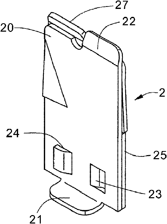
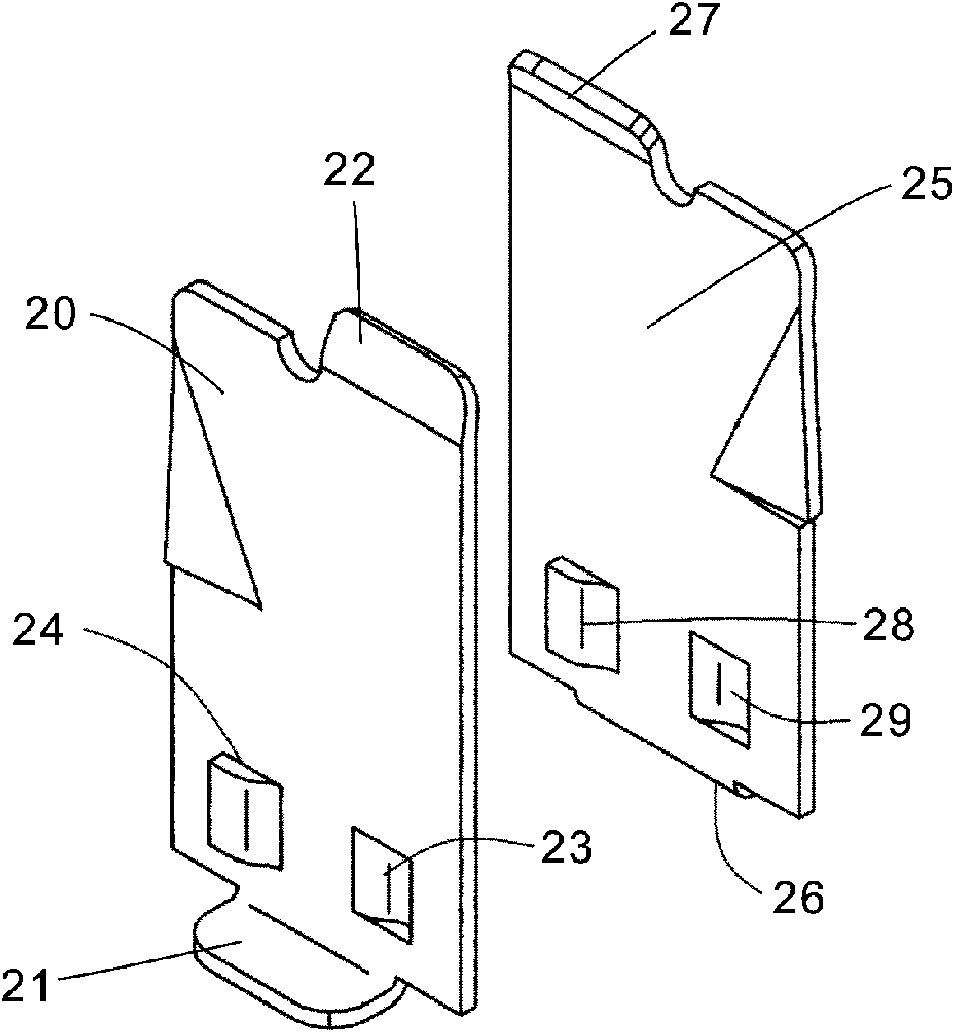
[0022] Example 1, see figure 2 and image 3 A male terminal 2 of an electric connector described in this embodiment has an A conductive sheet 20 and a B conductive sheet 25 arranged close to each other, and an A platform 21 and a An A conducting part 22, a B platform 26 and a B conducting part 27 are respectively designed at the two ends corresponding to the B conductive sheet 25, and an A bump 23 and an A groove 24 are designed on the A conductive sheet 20, Corresponding to the number and shape of the A bump 23 and the A groove 24 designed on the A conductive sheet 20, a B bump 28 and a B groove 29 are designed on the B conductive sheet 25, and the A on the A conductive sheet 20 The bump 23 protrudes into the B groove 29 on the B conductive sheet 25 to form an overcapacity fit, and the B bump 28 on the B conductive sheet 25 protrudes into the A groove 24 on the A conductive sheet 20 to form an overcapacity fit . The A bump 23 and the B bump 28 are trapezoidal in cross-sec...

Embodiment 2

[0029] Example 2, see Figure 4 and Figure 5 The female terminal 3 of an electrical connector described in this embodiment has a C conductive sheet 30 and a D conductive sheet 35 arranged close to each other, and a C platform 31 and a C platform 31 are respectively designed at the two ends of the C conductive sheet 30. A C conductive part 32, a D platform 36 and a D conductive part 37 are respectively designed at the two ends corresponding to the D conductive sheet 35, a C groove 33 and a D groove 34 are designed on the C conductive sheet 30, Corresponding to the number and shape of the C groove and the D groove 34 designed on the C conductive sheet 30, a C bump 38 and a D bump 39 are designed on the D conductive sheet 35, and the C bump 39 on the D conductive sheet 35 The block 38 protrudes into the C groove 33 on the C conductive sheet 30 to form an overcapacity fit, and the D bump 39 on the D conductive sheet 35 protrudes into the D groove 34 on the C conductive sheet 30 ...


PUM


Abstract

The invention relates to an electric connector terminal and a manufacturing method thereof, and belongs to the field of electric connectors. The electric connector terminal is provided with two conductive sheets which are tightly attached to each other, wherein the two corresponding ends of each conductive sheet are respectively provided with a platform and a conductive connecting part; one conductive sheet is provided with more than one bump and/or more than one groove, and the other conductive sheet is provided with more than one groove and/or more than one bump with the number and shape corresponding to those of the bump and/or the groove formed on one conductive sheet; and the bumps correspond to and are matched with the grooves one by one, and the bumps on one conductive sheet stretch into the grooves on the other conductive sheet to form interference fit. The manufacturing method comprises the following steps of: molding the two conductive sheets, attaching, punching to mold the bumps and the grooves, and calendering the bumps. The electric connector terminal has a firm structure and is convenient to assemble; and by the method, the two conductive sheets can be punched at one time and the bumps and the grooves on the two conductive sheets can be molded simultaneously, so that molding times is reduced.

Description

technical field [0001] The invention relates to the field of electrical connectors, in particular to an electrical connector terminal with two conductive sheets and a manufacturing method thereof. Background technique [0002] At present, in order to meet the needs of high-speed and stable electrical connection between two electronic devices, conductive solder balls are used to connect conductive terminals and printed circuit boards. In the application of electrical connectors, in order to ensure the force balance of the terminals, it is often required that the terminals and solder balls be installed at the center of the terminal holes. US Patent Application No. US6024584 discloses a terminal with an L-shaped tail, the L-shaped tail is for receiving solder balls. Although this patent discloses a structure in which the terminal is arranged at the center of the terminal hole, it does not design a platform to receive the solder ball, but needs to provide a notch on the outside...

Claims


Application Information

Patent Timeline
IPC IPC(8): H01R13/02H01R4/26H01R43/16
Inventor 邓玉泉
Owner 奕东电子科技股份有限公司
Why Eureka
Try Eureka