Automatic circular welding machine for plate roller plug

A plug, automatic technology, used in welding equipment, auxiliary welding equipment, welding/cutting auxiliary equipment, etc. Concentricity of the circle, the gap between the plug and the pipe is not easy to control, etc., to achieve the effect of reducing the turning allowance, good dynamic balance performance, and reducing material consumption

Inactive Publication Date: 2011-05-11
SHANGHAI YUNCHENG PLATE MAKING
View PDF5 Cites 17 Cited by
  • Summary
  • Abstract
  • Description
  • Claims
  • Application Information

AI Technical Summary

Problems solved by technology

[0003] 1. Because the diameter of each plate roller is different, the matching gap between the plug and the pipe is not easy to control, so the concentricity between the center hole of the plug and the outer circle of the pipe is quite different
Ultimately affects the accuracy of the plate roller
[0004] 2. Due to errors such as ellipse, bending, and uneven wall thickness in the pipe, which affect the concentricity between the center hole of the plug and the outer circle of the pipe, the lathe workers usually have to manually adjust the outer circle of the roller during processing to ensure that the roller can be turned
[0005] 3. The error between the center hole of the plug and the outer circle of the pipe will make the wall thickness of the processed version roller uneven, and the version roller will be heavier, which will affect the uneven printing effect of the version roller

Method used


Image

  • Automatic circular welding machine for plate roller plug
  • Automatic circular welding machine for plate roller plug
  • Automatic circular welding machine for plate roller plug

Examples


Embodiment Construction

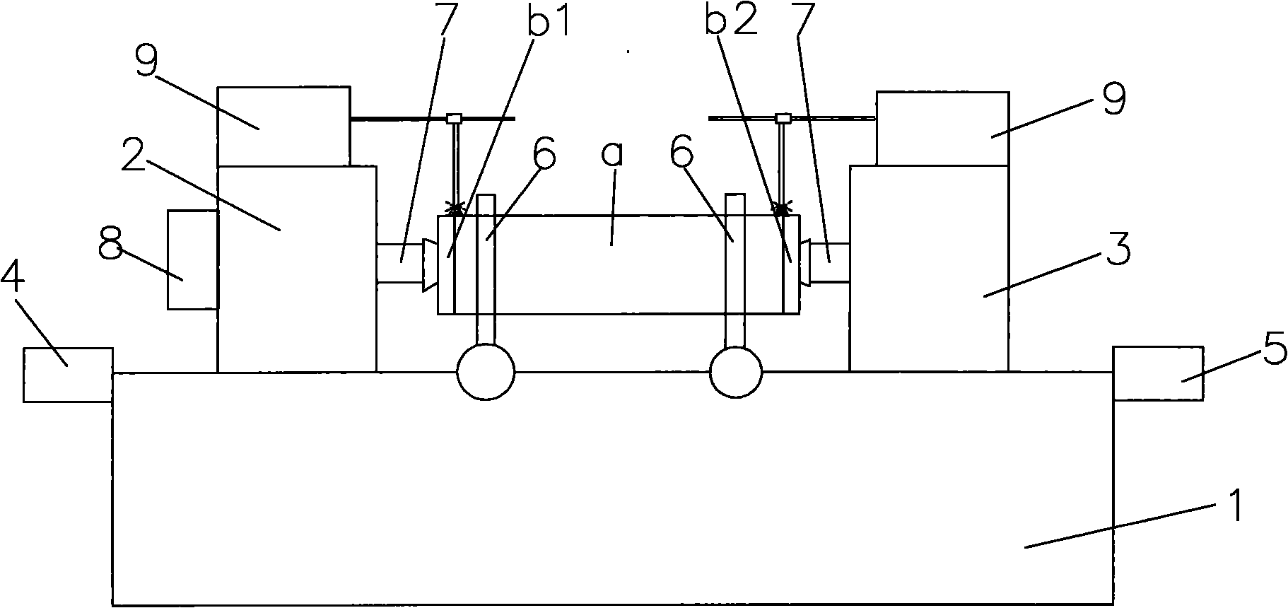
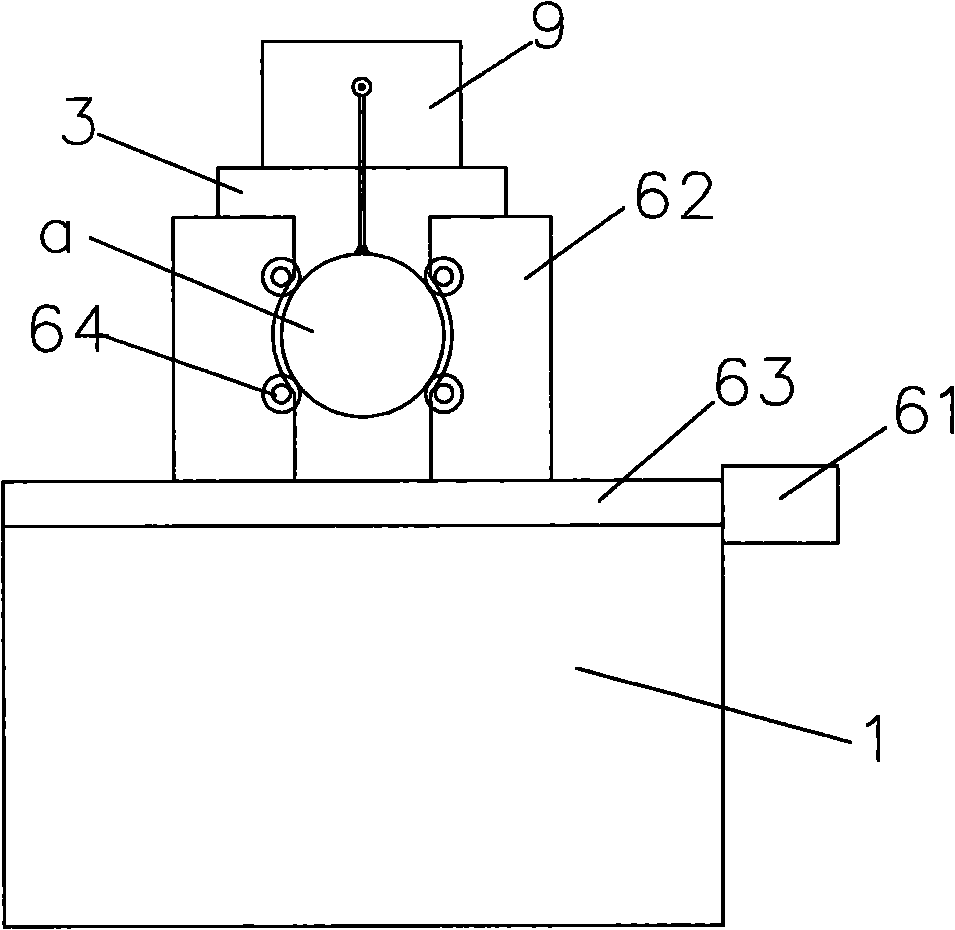
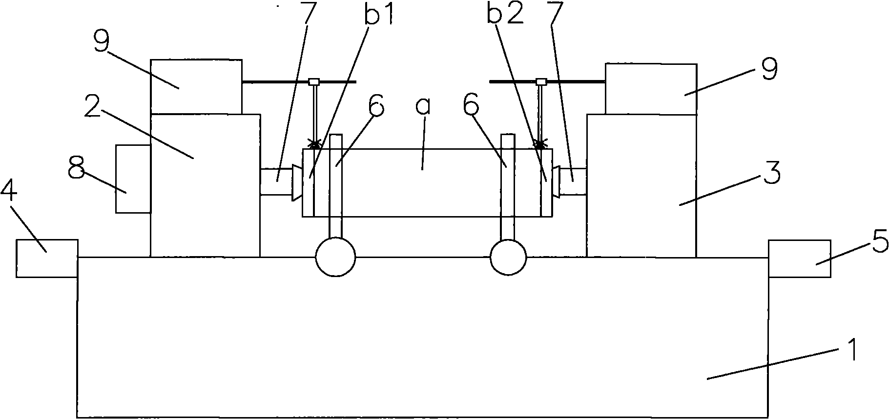
[0016] see figure 1 , the version roller plug automatic ring welding machine of the present invention comprises a bed 1, a bedside box 2 installed at the head of the bed and a tailstock 3 installed at the end of the bed, and the bedside is provided with a drive for driving the headstock 2 to move left and right The first deceleration motor 4 is provided with the second deceleration motor 5 for driving the tailstock 3 to move left and right at the end of the bed, and also includes two four-wheel alignment center frames 6, two tops 7, the third deceleration motor 8 and two welding machines 9. Two four-wheel positioning center frames 6 are arranged at intervals in the middle of the bed for positioning the pipe a. The two tops 7 are respectively rotatably installed on the headstock and the tailstock and are arranged opposite to each other. The third reduction motor 8 is installed on the bedside box and links to each other with the top drive installed on the bedside box and can dri...


PUM


Abstract

The invention provides an automatic circular welding machine for a plate roller plug. The circular welding machine comprises a lathe bed, a head stock and a tail seat, wherein a machine head is provided with a first speed-reducing motor; and a tail stock is provided with a second speed-reducing motor. The circular welding machine further comprises two four-wheel positioning centre frames, two finals, a third speed-reducing motor and two welding machines, wherein the two four-wheel positioning centre frames are arranged in the middle of the lathe bed at intervals; the two finals are rotationally arranged on the head stock and the tail seat respectively and oppositely; the third speed-reducing motor is installed on the head stock and connected with the finals arranged on the head stock in atransmission mode; and the two welding machines are respectively arranged above the head stock and the tail seat. In the invention, the excircle of a pipe and the centre hole of the plug are taken aspositioning references, the excircle of the pipe is centered by the four-wheel positioning centre frames, the centre hole of the plug is centered by the finals, and the centers of the four-wheel positioning frames and the two finals are in the same horizontal line. Thus, the concentricity of the centre hole of the plug and the excircle of the pipe is ensured, thereby ensuring the welding quality.

Description

technical field [0001] The invention relates to a welding device, in particular to an automatic ring welding machine for plate roller plugging. Background technique [0002] During the production process of the printing plate roller, two plugs are welded to the two ends of the pipe respectively, and the plugs are provided with a central hole for installing the shaft. In order to ensure the concentricity of the plug and the pipe, the current method is usually to assemble the plug with the pipe after turning the inner and outer circles of the plug and then perform ring welding. The problems with this welding method are: [0003] 1. Because the diameter of each plate roller is different, the matching gap between the plug and the pipe is not easy to control, so the concentricity between the center hole of the plug and the outer circle of the pipe is quite different. Ultimately affect the accuracy of the plate roller. [0004] 2. Due to errors such as ellipse, bending, and une...

Claims


Application Information

Patent Timeline
Patent Type & Authority Applications(China)
IPC IPC(8): B23K37/053B23K37/047
Inventor 姚根龙
Owner SHANGHAI YUNCHENG PLATE MAKING
Why Eureka
Try Eureka