Parallel link robot

一种机器人、连杆的技术,应用在机械手、机械设备、程序控制机械手等方向,能够解决吸盘易与工件W干涉、加长安装部件190与吸盘780距离、电缆卷绕在其它部件上等问题

Active Publication Date: 2011-05-11
FANUC LTD
View PDF7 Cites 40 Cited by
  • Summary
  • Abstract
  • Description
  • Claims
  • Application Information

AI Technical Summary

Problems solved by technology

[0016] However, since the rotation absorbing unit 800 is disposed between the suction cup 780 and the mounting member 190, the distance between the mounting member 190 and the suction cup 780 needs to be lengthened.
Therefore, in the prior art, there is a problem that the chuck 780 is enlarged and easily interferes with the workpiece W.
Furthermore, when using an end effector to which the rotation absorbing unit 800 cannot be attached, or when a cable for the end effector is required, there is also a problem that when the drive of the additional driver 130d etc. Problems with associated piping, e.g. air pipes or wiring, e.g. cables wrapped around other components

Method used


Image

  • Parallel link robot
  • Parallel link robot
  • Parallel link robot

Examples


Embodiment Construction

[0040] Hereinafter, embodiments of the present invention will be described with reference to the drawings. The same reference numerals are assigned to the same components in the following figures. In order to facilitate understanding, these drawings are appropriately changed in scale.

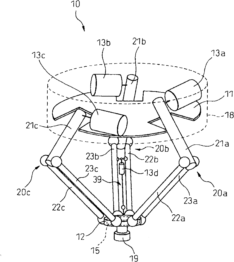
[0041] figure 1 It is a perspective view of a parallel link robot according to a typical embodiment of the present invention. exist figure 1 Among them, the parallel link robot 10 mainly includes: a base part 11 installed in a casing 18 ; a movable plate 12 ; and three link parts 20 a - 20 c connecting the base part 11 and the movable plate 12 . A mounting member 19 is provided under the movable plate 120 , and an unshown end effector is mounted on the mounting member 19 .

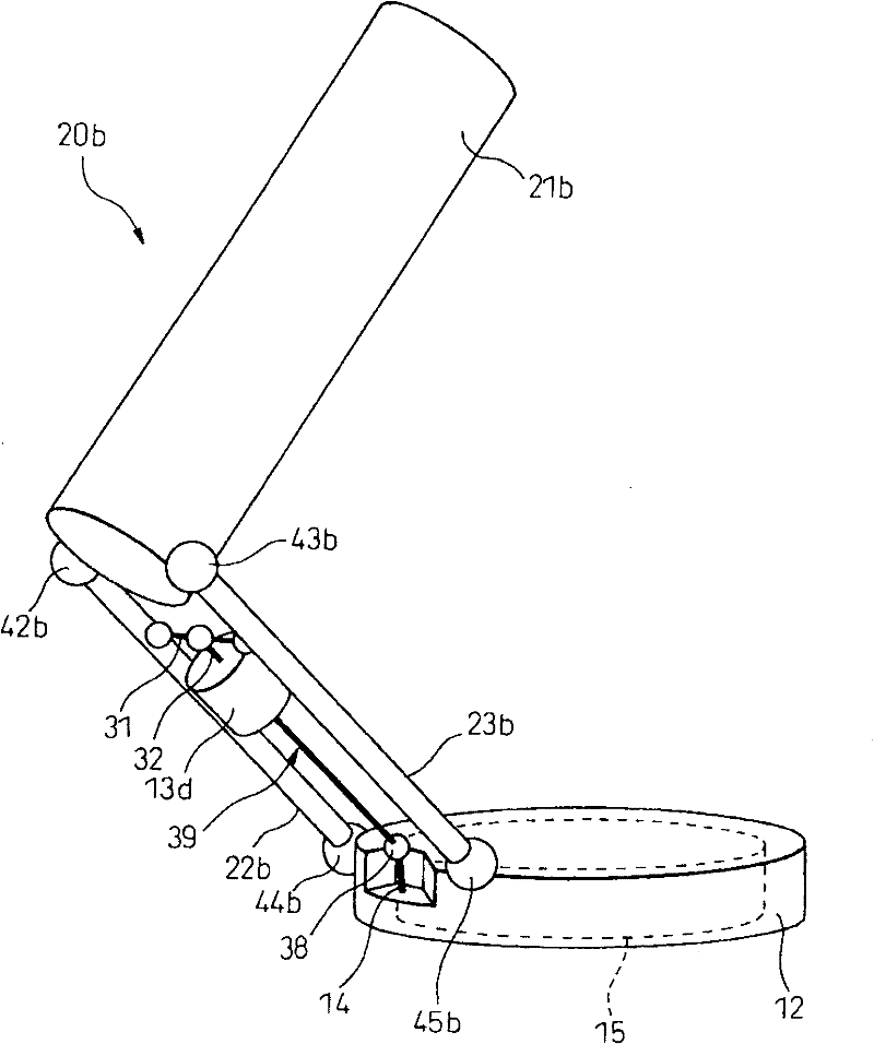
[0042] figure 2 yes figure 1 A partial perspective view of the parallel-link robot shown. Such as figure 2 As shown, the link portion 20b includes a drive link 21b and two driven links 22b, 23b extending from t...


PUM


Abstract

A parallel link robot (10) provided with a base (11), a moving part (12), three links (20a to 20c) coupling the base and the moving part and having respectively single degrees of freedom with respect to the base, and three actuators (13a to 13c) respectively driving the links, each of the links comprised of a drive link (21a to 21c) coupled with the base and two driven links (22a to 22c, 23a to 23c) coupling the drive link and the moving part and parallel to each other, and further provided with a posture changing mechanism (15) which changes a posture of an element (19) attached to the moving part, an additional actuator (13d to 13f) arranged between the two driven links of at least one link in parallel to these driven links, and a power transmission shaft (39) which extends coaxially from the additional actuator and transmits rotational drive force to the posture changing mechanism. Due to this, it is possible to increase the degrees of freedom without reducing the possible region of operation and the acceleration / deceleration performance.

Description

technical field [0001] The present invention relates to a parallel link robot using a delta-type parallel link mechanism for three-dimensionally positioning a mounting member included in an end effector. Background technique [0002] Figure 11 is a perspective view of a parallel link robot in the prior art. Such as Figure 11 As shown, the prior art parallel link robot 100 mainly includes a base part 110 , a movable plate 120 and three link parts 200 a - 200 c connecting the base part 110 and the movable plate 120 . Furthermore, an unillustrated end effector mounting member 190 is provided on the movable plate 120 . [0003] From Figure 11 It can be seen that the connecting rod part 200a includes a driving connecting rod 210a extending from the base part 110 and two driven connecting rods 220a, 230a extending from the movable plate 120, and these connecting rods are connected to each other by spherical bearings. Also, the base part 110 includes a driver 130a that drives ...

Claims


Application Information

Patent Timeline
Patent Type & Authority Applications(China)
IPC IPC(8): B25J9/10
CPCB25J17/0266B25J9/0051Y10T74/20305Y10T74/20329Y10T74/20207
Inventor 木下聪永山智昭山本真广榑林秀伦藤本胜巳上村时敬
Owner FANUC LTD
Why Eureka
Try Eureka