Guide pipe machining lathe

A technology of lathes and ducts, applied in metal processing equipment, turning equipment, turning equipment, etc., can solve problems such as low production efficiency, high equipment investment and labor costs, and reduce the concentricity of intake ducts, so as to save processing costs and improve The effect of work efficiency

Inactive Publication Date: 2010-04-28
CHONGQING ZHIBO POWDER METALLURGY
View PDF0 Cites 30 Cited by
  • Summary
  • Abstract
  • Description
  • Claims
  • Application Information

AI Technical Summary

Problems solved by technology

This processing method mainly has the following disadvantages: 1. The required processing equipment is large, the number of operators is large, and the equipment investment and labor costs are high; 2. The same work...

Method used


Image

  • Guide pipe machining lathe
  • Guide pipe machining lathe
  • Guide pipe machining lathe

Examples


Embodiment Construction

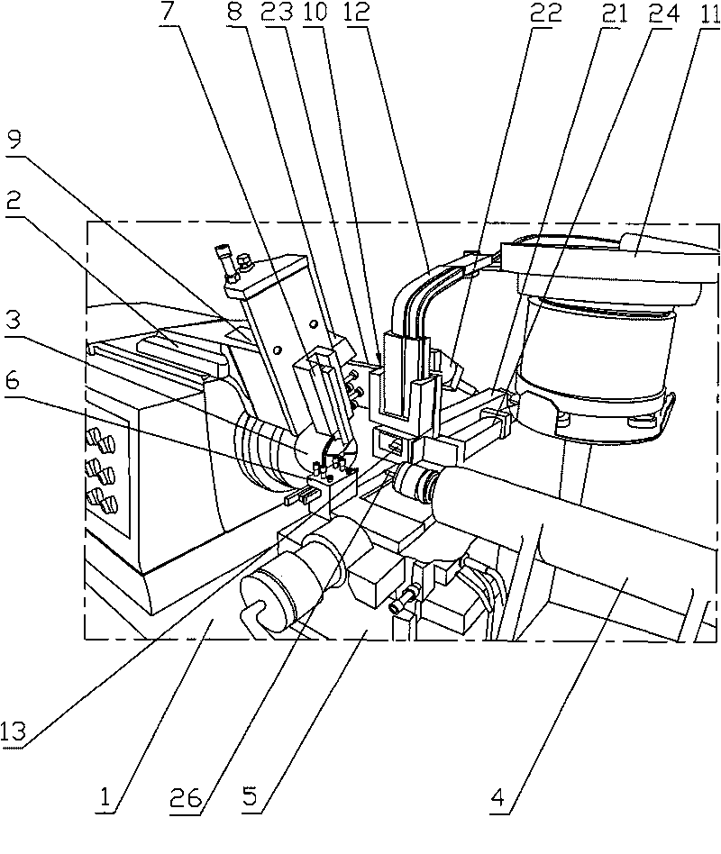
[0022] The present invention will be described in further detail below in conjunction with the accompanying drawings and specific embodiments.

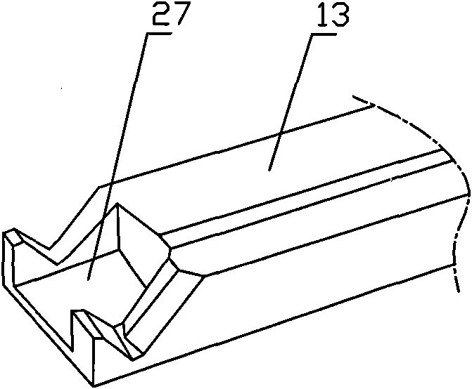
[0023] figure 1 It is a structural schematic diagram of the present invention, figure 2 It is a structural schematic diagram of the workpiece positioning plate, as shown in the figure: the tube machining lathe includes body 1, headstock 2, chuck 3, tailstock 4, slide plate 5, main tool rest 6, secondary tool rest 7, secondary tool rest drive hydraulic pressure Cylinder 8, automatic loading mechanism 10 and automatic blanking mechanism. The secondary tool rest drive hydraulic cylinder 8 is fixedly arranged on the spindle box 2, and the inclined downward track 9 is arranged on the spindle box 2. The secondary tool rest 7 is installed on the track 9 and is pushed along by the piston rod of the secondary tool rest drive hydraulic cylinder 8. The track 9 slides with a single degree of freedom; the secondary tool rest 7 is provided with ...


PUM


Abstract

The invention discloses a guide pipe machining lathe, which comprises a main shaft box, a chuck, a tail seat, a primary tool rest, a secondary tool rest and a secondary tool rest driving hydraulic cylinder. The secondary tool rest driving hydraulic cylinder is fixedly arranged on the main shaft box, a downward inclined track is arranged on the main shaft box, the secondary tool rest is arranged on the track and is driven by the secondary tool rest driving hydraulic cylinder to slide along the track in single degree of freedom, the secondary tool rest is provided with at least two lathe tools along the central line of the chuck, and the tool noses of the lathe tools point to the central line of the chuck obliquely downwards; and the primary tool rest is provided with at least two lathe tools along the central line of the chuck. By arranging the secondary tool rest and the lathe tools on the main shaft box to feed, groove and machine inlet and exhaust guide pipes of a motorcycle engine and arranging the lathe tools on the primary tool rest to longitudinally feed and cut the inlet guide pipes, the purpose of completely machining and shaping machined pieces once is achieved only by clamping the machined pieces once, the work efficiency is greatly improved, and the machining cost is saved. Meanwhile, the machined pieces are automatically fed and clamped and automatically popped and discharged, and the whole machining process realizes full automatic operation.

Description

technical field [0001] The invention relates to a machining device, in particular to a conduit processing lathe suitable for finishing the intake and exhaust conduits of motorcycles. Background technique [0002] 125 ducts are widely used as the intake and exhaust pipes of motorcycle engines, and its manufacturing process mainly includes three parts: 1. Press the metal powder with a powder product hydraulic press to form a model of 125 ducts; 2. Heat and fire the model of 125 ducts , to fuse the pressed metallurgical powder; 3. Carry out metal cutting processing. [0003] In the prior art, the air intake duct is processed by C616 lathe and micro lathe CH300 and other equipment. It needs 9 processing procedures to complete. Only the processing of the head requires 3 procedures, 3 operators, and 3 processing equipment. tower. This processing method mainly has the following disadvantages: 1. The required processing equipment is large, the number of operators is large, and the...

Claims


Application Information

Patent Timeline
IPC IPC(8): B23B5/08
Inventor 孙万里李盛林
Owner CHONGQING ZHIBO POWDER METALLURGY
Why Eureka
Try Eureka