Light fitting

A technology of lamps and chambers, which is applied in the direction of damage prevention measures for lighting devices, lighting devices, cooling/heating devices for lighting devices, etc., and can solve problems such as light decay, affecting service life, affecting air circulation effects, and heat dissipation efficiency. Achieve the effects of avoiding light decay, prolonging service life, improving airflow and heat dissipation

Inactive Publication Date: 2011-05-11
SUNONWEALTH ELECTRIC MACHINE IND
View PDF6 Cites 4 Cited by
  • Summary
  • Abstract
  • Description
  • Claims
  • Application Information

AI Technical Summary

Problems solved by technology

However, the space above the ceiling and the concrete floor slab of the building itself is generally closed, this space is not easy to circulate with outside air, and other items (such as pipes, lines or heat insulation materials) may be placed in this space , thus affecting its air circulation effect and heat dissipation performance
[0004] As mentioned in the previous paragraph, due to the poor heat dissipation efficiency of the existing structure, it is easy to cause the heat accumulation problem of the annular heat sink, resulting in that the heat generated by each light-emitting element cannot be smoothly removed, so that each light-emitting element and its chip are in a long time. High temperature environment affects its service life
Moreover, when the chip of each light-emitting element is overheated, it will cause light decay, which will affect the luminous efficacy of each light-emitting element.

Method used


Image

  • Light fitting
  • Light fitting
  • Light fitting

Examples


Embodiment Construction

[0044] In order to make the above-mentioned and other objects, features and advantages of the present invention more comprehensible, the preferred embodiments of the present invention are specifically cited below, together with the accompanying drawings, as follows:

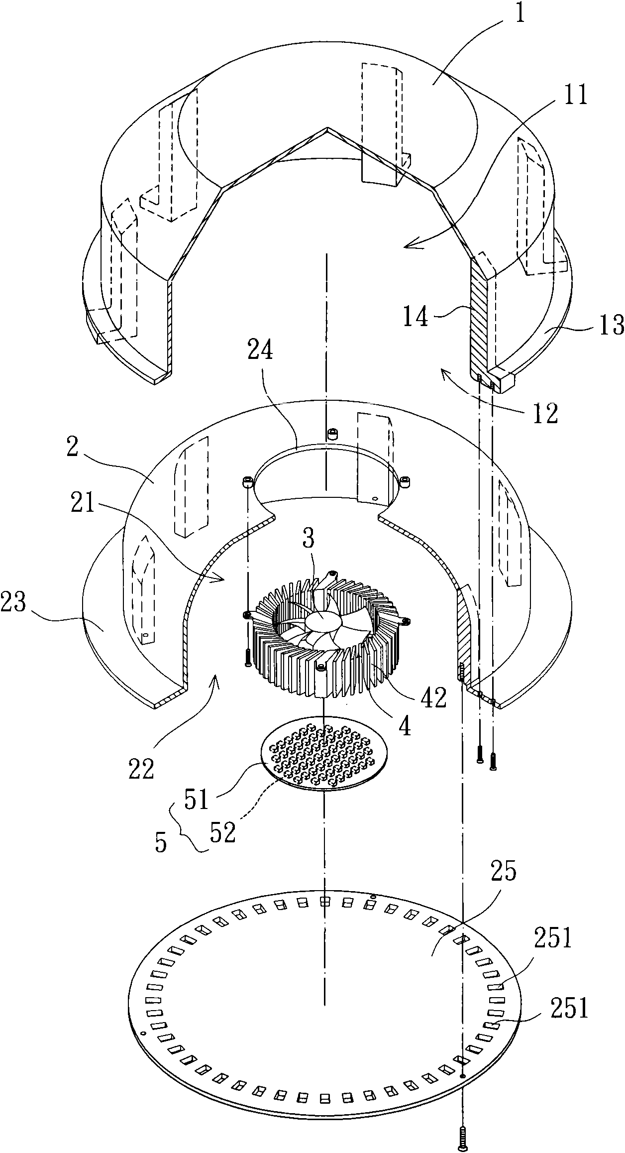
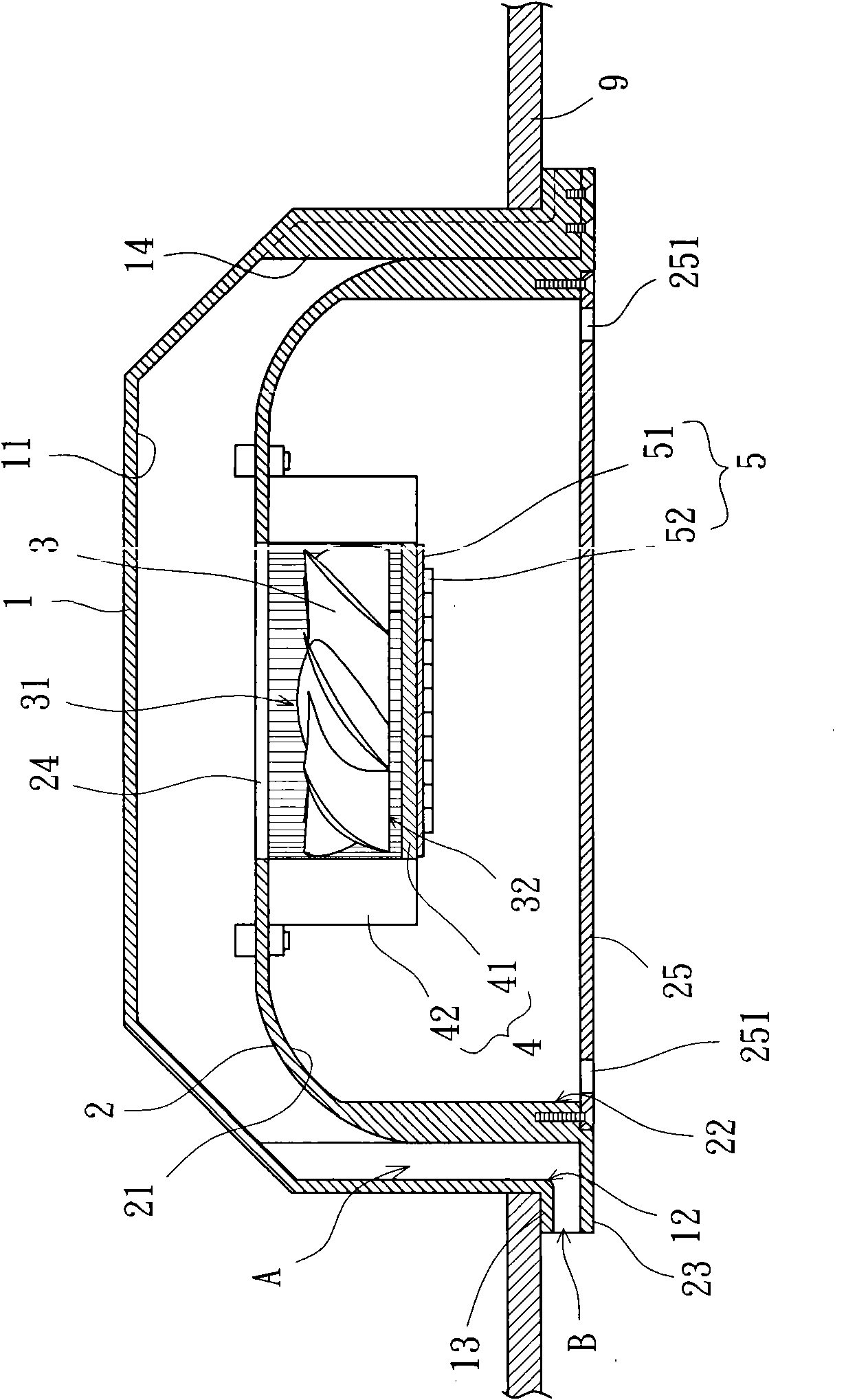
[0045] Please refer to figure 1 and 2 As shown, the lamp according to the first embodiment of the present invention includes an outer cover 1 , an inner shell seat 2 , a fan 3 , a heat sink 4 and a light emitting element 5 . Wherein, the inner shell base 2 is arranged in the outer cover 1, and an airflow channel A is formed between the outer cover 1 and the inner shell base 2, the fan 3 is arranged in a through hole 24 adjacent to the inner shell base 2, and the radiator 4 and the light-emitting element 5 are arranged in the inner shell seat 2, so that when the fan 3 is running, the airflow can be driven to circulate between the airflow passage A and the interior of the inner shell seat 2 through the through hol...


PUM


Abstract

The invention discloses a light fitting which comprises an outer cover, an inner shell seat, a fan, a radiator and a light-emitting element, wherein the outer cover is provided with a first accommodating chamber and a first opening; the inner shell seat is provided with a second accommodating chamber and a second opening, and is additionally provided with a through hole; the through hole is communicated with the first accommodating chamber and the second accommodating chamber; the inner shell seat is arranged in the first accommodating chamber; the second opening and the first opening are opposite; an interval is formed between the outer cover and the inner shell seat so as to form an air flow passage; the fan is adjacent to the through hole; the fan is provided with two air flow circulation sides; the two air flow circulation sides are used for inhaling and blowing out air flow, so that the air flow passes the through hole; and one side of the bottom plate of the radiator faces the fan, and the other side of the bottom plate of the radiator is provided with the light-emitting element. According to the invention, preferable air flow circulation and heat dissipation efficiency can be provided so as to avoid the influences on the service life and luminous efficacy of the light fitting.

Description

technical field [0001] The present invention relates to a lamp, especially a lamp embedded in the ceiling to provide indoor or outdoor lighting. Background technique [0002] The existing embedded lamp structure, as shown in Taiwan Patent Publication No. M359644 "Lamp Heat Dissipation Device", includes a base plate, an annular heat sink, a fan and a shell cover. The substrate has two surfaces, one of which is provided with several light-emitting elements, and the other surface can be combined with the annular cooling seat, and several air holes pass through between the two surfaces of the substrate, and the fan is installed on the annular cooling seat , the shell cover is arranged on the outside of the annular heat sink and the fan and combined with the base plate, so that the surface of the base plate with the light-emitting element faces outward. Since the case cover is provided with several ventilation slots, when the fan is running, the airflow can be driven to enter th...

Claims


Application Information

Patent Timeline
IPC IPC(8): F21S8/02F21V15/02F21V29/02F21Y101/02F21V29/67F21V29/76F21V29/83
Inventor 洪银树宫原雅晴李明聪赖思豪
Owner SUNONWEALTH ELECTRIC MACHINE IND
Why Eureka
Try Eureka