Unmanned management method and system for test equipment

A test equipment, microprocessor technology, applied in the direction of instruments, comprehensive factory control, electrical program control, etc., can solve the problems of limited number of network interfaces, cumbersome wiring, etc., to ensure the safety of life and property, avoid accidents, and improve the economy. effect of benefit

Active Publication Date: 2013-04-24
QIMING INFORMATION TECH
View PDF4 Cites 0 Cited by
  • Summary
  • Abstract
  • Description
  • Claims
  • Application Information

AI Technical Summary

Problems solved by technology

[0004] The invention discloses an unmanned management method for test equipment, which has the advantages of fast communication speed, good real-time performance and simple wiring, solves the problems of limited number of network interfaces and cumbersome wiring, and realizes uninterrupted real-time monitoring of the operating status of test equipment. Monitoring and Fault Alerting

Method used


Image

  • Unmanned management method and system for test equipment
  • Unmanned management method and system for test equipment

Examples


Embodiment 1

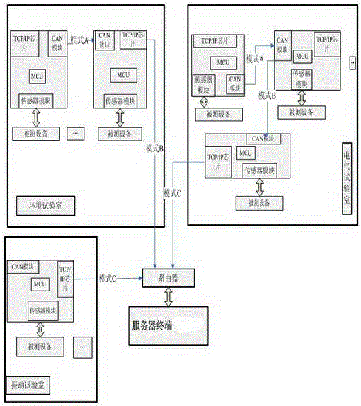
[0034] There are three main modes for differential signal transmission to the server terminal (computer) display (mode A or mode B or mode C):

[0035] Mode A, the CAN module in the information acquisition unit directly uploads the differential signal of the running test equipment to the CAN interface;

[0036] Mode B. The CAN interface in the information collection unit obtains the differential signal on the CAN interface of other information collection units in the CAN network, and at the same time uploads the differential signal on its own test equipment to the CAN network, and the microprocessor MCU obtains the differential signal. Through TCP / IP interface uploads the signal to the server terminal (computer);

[0037] Mode C. The information collection unit uploads the differential signal of the running test equipment to the server terminal (computer) through the TCP / IP interface. (see figure 1 )

[0038] Example 2

Embodiment 2

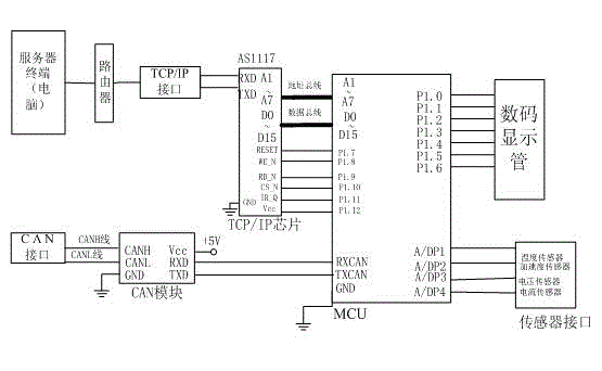
[0040] The CANH terminal and CANL terminal of the CAN module are respectively connected to the CANH line and the CANL line of the CAN interface to complete the differential signal transmission of the CAN line to the CAN interface, mainly through transmission mode A and mode B for differential signal transmission: mode A, information acquisition unit The CAN module of the CAN module directly uploads the differential signal of the running test equipment to the CAN interface; in mode B, the CAN interface in the information acquisition unit obtains the differential signal on the CAN interface of other information acquisition units in the CAN network, and at the same time uploads the differential signal on the own test equipment The differential signal is uploaded to the CAN network, the microprocessor MCU obtains the differential signal, and uploads the signal to the server terminal (computer) through the TCP / IP interface.

[0041] The TCP / IP chip (DM9000 model used in this example...


PUM


Abstract

The invention discloses an unmanned management method and system for test equipment. The system is formed by the connection of a plurality of information acquisition units with a server through a router. Each information acquisition unit comprises a sensor, a micro processing unit (MCU), a controller area network (CAN) module and a transmission control protocol (TCP) / Internet protocol (IP) chip. An acquired analog signal of test equipment is sent to the MCU by the sensor through an A / D interface, amplification, data processing and logic judgment are carried out on a digital signal, the processed digital signal is converted into a differential signal by the CAN module and sent to a CAN interface, and the differential signal is then received and analyzed by the TCP / IP chip and transmitted by a TCP / IP interface, so that the method for the uninterrupted real-time monitoring of the running state of the test equipment and failure alarm is realized. The signal of the test equipment is mainlytransmitted with the method of building a local area network through combining a CAN technology and a TCP / IP technology. The method has the advantages of high communication speed, good real-time property and simplicity for wiring, and solves the problems of limited number of network interfaces, complicated wiring and the like.

Description

technical field [0001] The invention provides an unmanned management method for test equipment, and also discloses a system for realizing the method, which belongs to the field of online monitoring systems for test equipment. Background technique [0002] At present, the current situation of daily management of test equipment in small and medium-sized laboratories follows the traditional method: testers carry out daily management and maintenance of test equipment, and only carry out maintenance when the test equipment breaks down. There is no online monitoring system for test equipment when it is running. When the test equipment is running, once a certain control unit of the test equipment has a potential failure, we cannot predict it, and the potential failure information cannot be displayed to the tester in time, which will cause some safety hazards, reduce production efficiency, shorten The service life of the test equipment. [0003] To improve the reliability and safe...

Claims


Application Information

Patent Timeline
Patent Type & Authority Patents(China)
IPC IPC(8): G05B19/418G08B21/00
Inventor 董杨边增远陈兆莹韩润哲李禄源楮贵良代海婷黄兵徐刚
Owner QIMING INFORMATION TECH
Why Eureka
Try Eureka