Digital thermorelay

A thermal relay, digital technology, applied in thermal relays, relays, instruments, etc., can solve problems such as error, zero drift, alloy moving piece can not be restored to the original state, etc., to achieve the effect of correcting errors and protecting the motor

Inactive Publication Date: 2011-05-11
郭永明
View PDF0 Cites 4 Cited by
  • Summary
  • Abstract
  • Description
  • Claims
  • Application Information

AI Technical Summary

Problems solved by technology

[0002] At present, the known thermal relay consists of a bimetallic strip (alloy moving piece), a guide plate, a lever, a push rod, a switch, a current setting knob, a test key, etc. When the motor is overloaded, the alloy moving piece bends, and the alloy moving piece pushes the guide plate, The guide plate pushes the lever, and the push rod on the lever pushes the switch contact to move to the off position, so that the thermal relay switch is disconnected and the motor is protected. However, after the thermal relay is used for a period of time, the alloy moving piece will have a zero point drift, that is, the alloy moving piece It cannot be restored to the initial state, resulting in changes in the position of the guide plate and the lever, and finally the distance between the push rod and the disconnected position of the switch contact changes, resulting in a large error; ordinary thermal relays do not display the distance between the push rod and the disconnected position of the switch contact. There is no function of distance value and change value, and there is no function of correcting error. It can only make the thermal relay that does not work when the error is large and overloaded be used for a long time, causing a large number of motors protected by the thermal relay to burn out.

Method used


Image

  • Digital thermorelay
  • Digital thermorelay
  • Digital thermorelay

Examples


Embodiment Construction

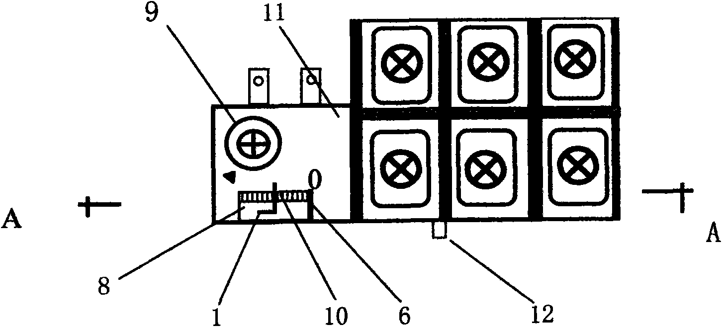
[0010] figure 1 It is a top view of the first embodiment of the present invention.

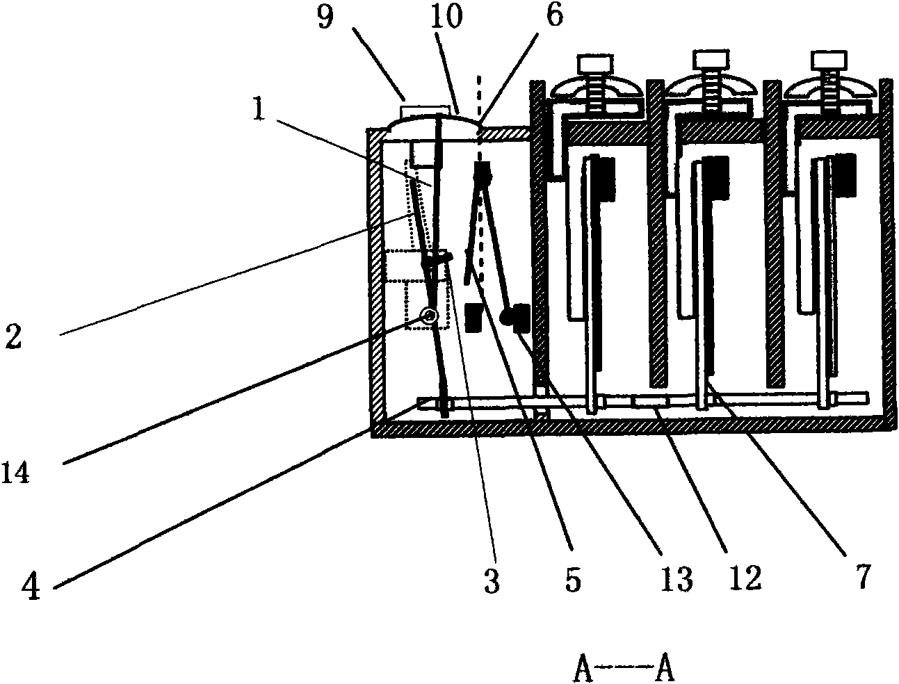
[0011] figure 2 yes figure 1 A-A cutaway view.

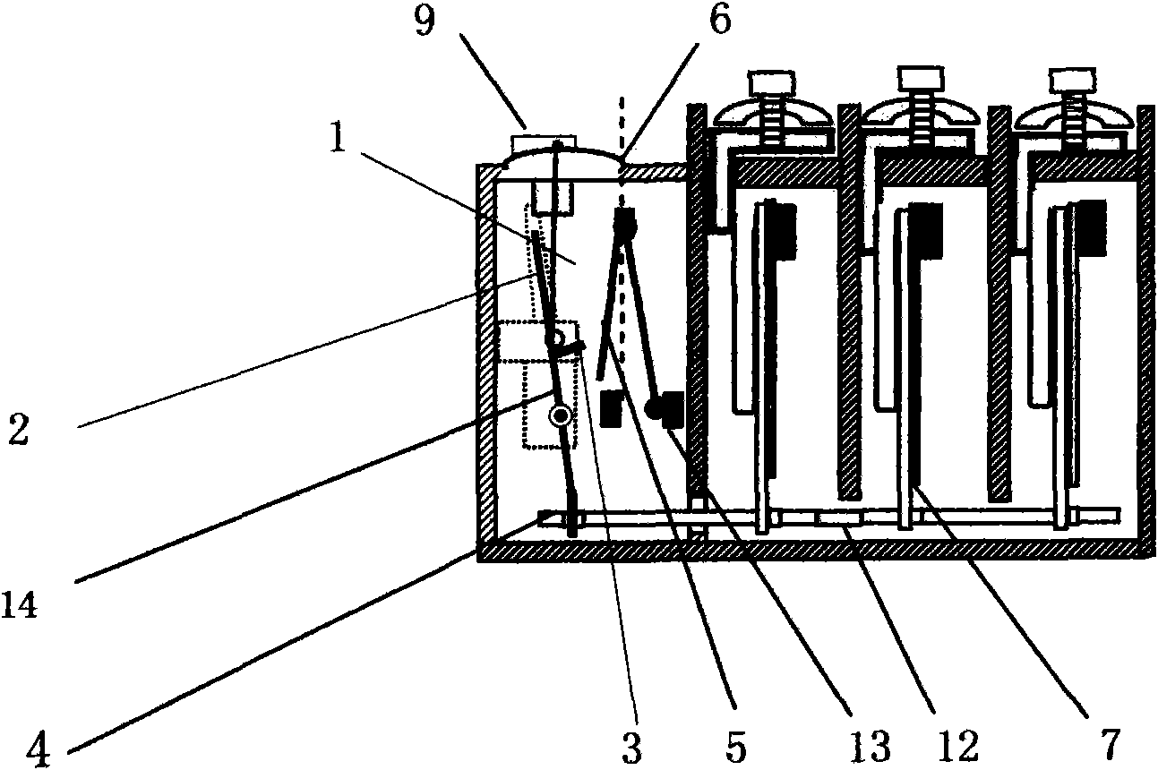
[0012] image 3 is the second embodiment

[0013] Figure 4 is the third embodiment

[0014] Figure 5 is a top view of another embodiment.

[0015] Figure 6 for Figure 5 The A-directed graph:

[0016] In the figure: 1. Pointer, 2. Lever, 3. Push rod, 4. Guide plate, 5. Switch contact, 6. Switch off position, 7. Alloy moving piece, 8. Rectangular hole, 9. Current setting knob , 10. Digital scale, 11. Adjustment panel, 12. Test key, 13. Switch, 14. Shaft

[0017] figure 1 : On the adjustment panel (11), there are digital scale (10), pointer (1), current setting knob (9), rectangular hole (8), test key (12), switch off position (6). The pointer table is composed of a pointer (1) and a digital scale (10). The number of the pointer 0 is the power-off position of the switch; the number displayed by the pointer table is 5, which indic...


PUM


Abstract

The invention relates to a digital thermorelay for protecting an electromotor, wherein an alloy rotor plate in a shell, a guide plate and a lever are connected in sequence; a push rod and a pointer are arranged on the lever; the length of the pointer is 5 times of the distance between a rotating shaft and the push rod; the error caused by zero point shifting of the alloy rotor plate guides the lever, the push rod and the pointer to rotate through the guide plate; finally, the distance between the push rod and the switch-off position of a switch is changed; the distance change is amplified for 5 times by a pointer meter formed by the pointer and a digital graduated scale; an electrician can judge the error of the thermorelay according to the digitals displayed on the pointer meter and can judge if the thermorelay can efficiently protect the electromotor and prevent the long-term use of the thermorelay which has big error and has no protective function; and a current setting knob can change the distance between the push rod and the switch-off position of and switch and can revise the error. The protective characteristic of the thermorelay capable of revising the error meets the standard and the protected electromotor is prevented from being burnt out caused by overload.

Description

Technical field [0001] The invention relates to a thermal relay for protecting a motor, in particular to a digital thermal relay capable of displaying the distance between a push rod and a disconnected position of a switch contact. Background technique [0002] At present, the known thermal relay consists of a bimetallic strip (alloy moving piece), a guide plate, a lever, a push rod, a switch, a current setting knob, a test key, etc. When the motor is overloaded, the alloy moving piece bends, and the alloy moving piece pushes the guide plate, The guide plate pushes the lever, and the push rod on the lever pushes the switch contact to move to the off position, so that the thermal relay switch is disconnected and the motor is protected. However, after the thermal relay is used for a period of time, the alloy moving piece will have a zero point drift, that is, the alloy moving piece It cannot be restored to the initial state, resulting in changes in the position of the guide pl...

Claims


Application Information

Patent Timeline
Patent Type & Authority Applications(China)
IPC IPC(8): H01H61/01G01D7/00
Inventor 郭永明
Owner 郭永明
Why Eureka
Try Eureka