Digital type thermal relay

A thermal relay, digital technology, applied in the field of digital thermal relay, can solve the problems of guide plate, lever position change, no correction error, thermal relay motor burnout, etc., to achieve the effect of correcting error, preventing large error, and protecting the motor

Inactive Publication Date: 2012-12-26
郭永明 +1
View PDF6 Cites 0 Cited by
  • Summary
  • Abstract
  • Description
  • Claims
  • Application Information

AI Technical Summary

Problems solved by technology

However, after the thermal relay is used for a long time, it will produce a large error and cannot effectively protect the motor. The reason is that due to the alternating changes of high and low temperatures, especially due to overcurrent, the temperature of the bimetal strip rises to the temperature of the phase transition point, and the bimetal strip The alloy moving piece must undergo a phase change, that is, the alloy structure and crystal arrangement change, resulting in a sharp change in the linear expansion coefficient of the alloy moving piece, and the internal stress (thermal stress, mechanical stress, residual stress) of the alloy moving piece Changes in the size and distribution of the alloy moving piece, changes in the internal stress cause changes in the physical quantities such as the elastic modulus and specific bending of the alloy moving piece, and the zero point drift of the alloy moving piece, that is, the alloy moving piece cannot return to the initial state, resulting in changes in the position of the guide plate and the lever. , and eventually the position of the push rod changes, and the distance between the push rod and the disconnected position of the switch contact changes; ordinary thermal relays do not have the function of displaying the distance and change value between the push rod and the disconnected position of the switch contact, nor error correction function
In this way, the thermal relay with large error and ineffectiveness can only be used for a long time, causing a large number of motors protected by the thermal relay to burn out

Method used


Image

  • Digital type thermal relay
  • Digital type thermal relay
  • Digital type thermal relay

Examples


Embodiment Construction

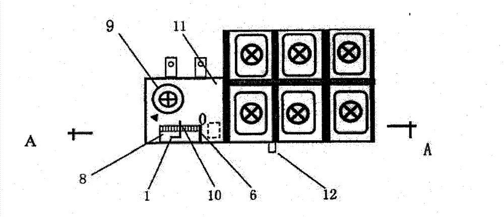
[0011] figure 1 It is a top view of the first embodiment of the present invention.

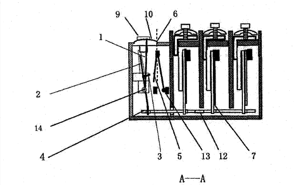
[0012] figure 2 yes figure 1 The A--A sectional view.

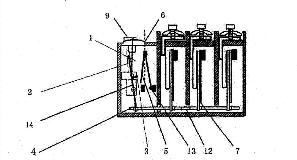
[0013] image 3 is the second embodiment

[0014] Figure 4 is the third embodiment

[0015] In the figure: 1. Pointer, 2. Lever, 3. Push rod, 4. Guide plate, 5. Switch contact, 6. Switch off position, 7. Bimetal, 8. Rectangular hole, 9. Current setting knob , 10. Digital scale, 11. Adjustment panel, 12. Test key 13. Switch, 14. Shaft

[0016] figure 1 : on the adjustment panel (11), there are digital scale (10), pointer (1), current setting knob (9); rectangular hole (8), test key (12), switch off position (6). The pointer table is composed of a pointer (1) and a digital scale (10). The number of the pointer 0 is the power-off position of the switch; the number displayed by the pointer table is 5, which indicates the distance between the push rod in the shell and the disconnected position of the switch contact (enlarge ) indic...


PUM


Abstract

The invention relates to a digital type thermal relay for protecting a motor. An alloy movable piece, a guide plate and a lever are sequentially connected in a casing, a push rod and a pointer are installed on the lever, and the length of the pointer is 5 times of a distance from a rotating shaft to the push rod; the lever, the push rod and the pointer rotate by an error caused by the zero drift of the alloy movable piece through the guide plate, a distance between the push rod and a disconnection position of a switch is changed finally, and the change of the distance is amplified by 5 times through a pointer table comprising the pointer and a digital scale. An electrician can judge the magnitude of the error of the thermal relay according to digits displayed by the pointer table and judgewhether the thermal relay effectively protects the motor or not. The long-term usage of the thermal relay which has large error and does not act as a protective action is prevented; a current calibration knob can be used for changing the distance between the push rod and the disconnection position of a contact point of the switch and can be used for modifying the error. The protective property ofthe thermal relay with the modified error meets the standard, and the protected motor can not be burnt out because of overload phase failure.

Description

Technical field [0001] The invention relates to a thermal relay for protecting a motor, in particular to a digital thermal relay capable of displaying the distance between a push rod and a disconnected position of a switch contact. Background technique [0002] At present, the known thermal relay consists of a bimetal, a guide plate, a lever, a push rod, a switch, a current setting knob, a test key, etc. When the motor is overloaded, the bimetal bends, the bimetal pushes the guide, the guide pushes the lever, and the lever The push rod on the top pushes the switch contact to move to the disconnected position, so that the switch is disconnected and the motor is protected. However, after the thermal relay is used for a long time, it will produce a large error and cannot effectively protect the motor. The reason is that due to the alternating changes of high and low temperatures, especially due to overcurrent, the temperature of the bimetal strip rises to the temperature of the...

Claims


Application Information

Patent Timeline
Patent Type & Authority Patents(China)
IPC IPC(8): H01H61/00H01H61/01
Inventor 郭永明
Owner 郭永明
Why Eureka
Try Eureka