
Array substrate and display

An array substrate and display technology, which is applied in the direction of instruments, electric solid-state devices, semiconductor devices, etc., can solve problems such as defects, abnormal screen display, and data line burnout, and achieve high compatibility, improve display quality, and improve display contrast. Effect

Inactive Publication Date: 2011-05-11
WINTEK CORP
View PDF0 Cites 3 Cited by
  • Summary
  • Abstract
  • Description
  • Claims
  • Application Information

AI Technical Summary

Problems solved by technology

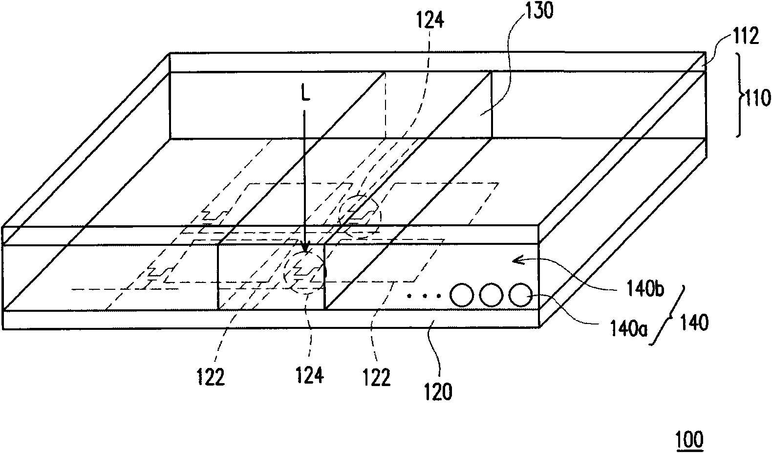
In this way, since the partition wall structure 130 is made of a transparent material, the light L passing through the transparent partition wall structure 130 will be incident on the transistor array substrate 120, which will cause light leakage and reflection of each metal film layer in the transistor array substrate, thereby reducing the display contrast. And the transistor 124 within its projection range will cause the carriers in the channel region of the transistor 124 to absorb the energy of the light L to generate a leakage current, resulting in abnormal screen display
If it is more serious, the instantaneous large leakage current will cause the data line electrically connected to it to be burned, resulting in line defects. Therefore, the existing electrophoretic display has the disadvantage that the transistor is susceptible to leakage current due to the influence of ambient light
[0004] From the above, it can be seen that the existing electrophoretic display cannot avoid the problems of leakage and reflection of external light and the leakage current of transistors affected by external light.

Method used


Image

  • Array substrate and display
  • Array substrate and display
  • Array substrate and display

Examples


Embodiment Construction

[0052] In order to make the objectives, technical solutions and advantages of the present invention clearer, the embodiments of the present invention will be further described in detail below with reference to the accompanying drawings. Here, the exemplary embodiments of the present invention and their descriptions are used to explain the present invention, but not to limit the present invention.

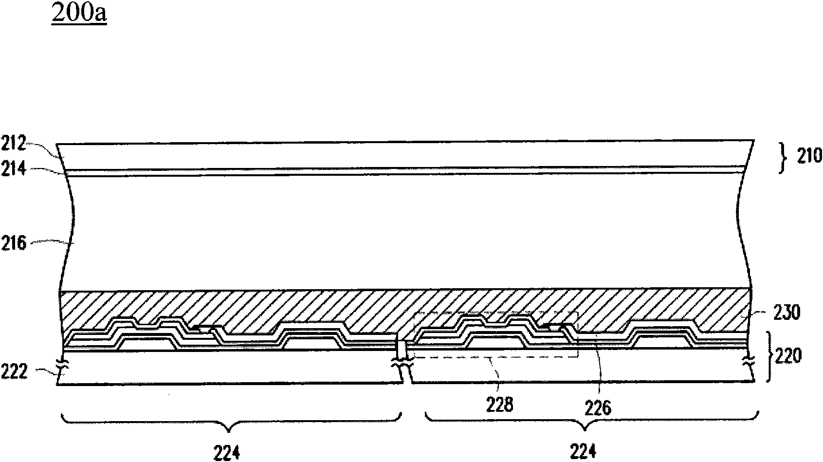
[0053] Figure 2A A schematic cross-sectional view of a high-contrast display according to an embodiment of the present invention is shown. Please refer to Figure 2A , the high contrast display 200 a of this embodiment mainly includes a first substrate 210 , a transistor array substrate 220 , a first electrode 214 , and a plurality of display media 216 . The transistor array substrate 220 is disposed opposite to the first substrate 210 . The first electrode 214 is located on the side of the first substrate 210 facing the transistor array substrate 220 . A plurality of display m...


PUM


Abstract

The invention discloses a display, which comprises a first substrate, a transistor array substrate and a shading layer, wherein the first substrate comprises a first electrode; the transistor array substrate comprises a plurality of pixels which are arranged in an array; each pixel comprises a transistor and a pixel electrode which is electrically connected with the transistor; a display medium is positioned between the first electrode and the pixel electrode; and the shading layer is positioned between the first substrate and the transistor. In the display, the shading layer can protect the transistor from generating light leakage current, so that displaying quality is enhanced.

Description

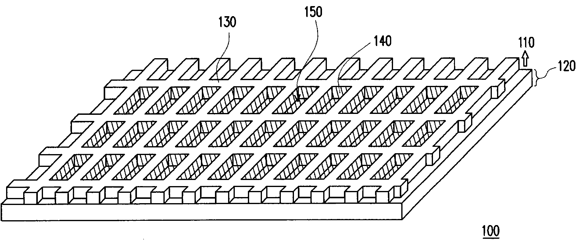
technical field [0001] The present invention relates to a display device, in particular to a high-contrast display. Background technique [0002] Figure 1A is a schematic top view of the cell structure in the above-mentioned conventional electrophoretic display, and Figure 1B for Figure 1A A partially enlarged perspective view of an existing electrophoretic display. Please refer to Figure 1A and Figure 1B , the material of the partition wall structure 130 in the conventional electrophoretic display 100 is a transparent material, and the display medium 140 filled in the microcellular structure 150 is composed of a black fluid 140b and a plurality of white particles 140a dispersed in the black fluid 140b constitute. like Figure 1B As shown, when the electric field between the pixel electrode 122 on the transistor array substrate 120 and the common electrode 112 on the electrophoretic substrate 110 changes, the white particles 140a will move up or down relative to the...

Claims


Application Information

Patent Timeline
Patent Type & Authority Applications(China)
IPC IPC(8): H01L27/02G02F1/167G02F1/1362
Inventor 康恒达王文俊
Owner WINTEK CORP
Learn More