Assembly for multiple connection in an electrical apparatus

A technology for electrical devices and components, which is applied to parts of connecting devices, conductive connections, electrical components, etc., can solve problems such as high voltage drop, affecting the modularity of electrical devices, and improper further engagement of screw heads

Active Publication Date: 2011-05-11
SCHNEIDER ELECTRIC IND SAS
View PDF6 Cites 9 Cited by
  • Summary
  • Abstract
  • Description
  • Claims
  • Application Information

AI Technical Summary

Problems solved by technology

In particular, since the height of the conventional connector clip 7 is fixed (constant), it should be designed to an appropriate size: too short, will make the screw 5 unable to separate completely from the clamp 3 during unscrewing; too short. long, will cause the screw head to separate from the conventional connector clip 7 in the fully tightened state, resulting in inappropriate further engagement of the clip 7 with the screw head
Furthermore, the dual channel structure is designed to utilize the maximum space of the upper lodging capability 4a, but this space is still partially occupied by the screw 5
Therefore, its main disadvantage is that it cannot be flexibly adapted to conductive parts of different capacities and sizes, nor can it provide uniform gripping (uniformgripping) between multiple conductive parts and fixed connectors, resulting in higher voltage drop
This in turn affects the modularity of electrical installations and requires complex and expensive arrangements resulting in elaborate, costly and bulky manufacturing
Also, the mounting of the headed screw 5 on the clip 6 requires clearance inside the assembly, causing the possibility of a slight tilt, therefore, the direct tightening of multiple connections with cables of different sizes ) may cause damage to conventional connector clips 6
In addition, some conventional methods cannot provide ingress safety protection

Method used


Image

  • Assembly for multiple connection in an electrical apparatus
  • Assembly for multiple connection in an electrical apparatus
  • Assembly for multiple connection in an electrical apparatus

Examples


Embodiment Construction

[0024] In order to simplify the description of the embodiments according to the present invention, the terminal assembly will be described corresponding to the insertion position shown in the drawings, wherein the channel for connecting the conductive member to the device is transverse for horizontal insertion, and the device Fastening of the internal electrical conductors is carried out by turning screws from the upper surface of the device. However, it should be understood that positional terms such as "horizontal", "top", "bottom" are in no way limiting to the object of the present invention. Also, geometric terms such as "orthogonal" and the like are to be understood in their mechanical sense, ie, with tolerances corresponding to strict mathematical definitions. Some expressions may be replaced by equivalent expressions, and shall be considered according to the functions they define in the technical features they represent.

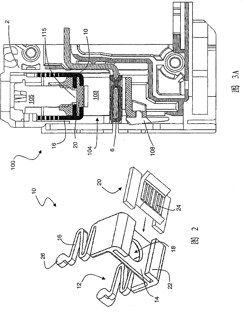
[0025] figure 2 An orthographic view of a fe...


PUM


Abstract

A terminal assembly (100) for multiple connection in an electrical apparatus comprises a protection plate (10) arranged with a resilient portion (12) and a base part provided with with a gripping profile on its surface. A clamp (103) is formed with a passage (104) for receiving and securing multiple electrical conductors. A fixed connector (6) is placed inside the clamp (103) in such a way that the passage of the clamp (103) is divided into an upper and lower housing portions to provide separate lodging for clamping the electrical conductors. A fastening means (105) is secured within the clamp (103) with its cylindrical or non-threaded tip contacting the base part of the protecting plate (10) and the fastening means (105) passing through a hole of a cooperating plate of said protecting plate (10), which is introduced into the passage of the clamp (103) in such a way that the resilient portion (12) of the protection plate (10) faces away from the clamp (103). The fastening means (105) is fastened on the clamp to press down the protection plate (10) such that the passage of the clamp (103) is adjusted in accordance with dimensional variations of the electrical conductors. Such assembly provides highest reliability and flexibility to achieve uniform and larger space for insertion of multiple electrical conductors.

Description

technical field [0001] This invention relates to the field of connection of electrical conductors to electrical devices such as circuit breakers. The invention relates in particular to assemblies for multiple connections in electrical installations. Background technique [0002] Many electrical applications require multiple connection terminal structures to provide lodging and clamping of multiple conductive members such as cables, busbars, electrical connections, and the like. In particular, it is suitable for the connection of multiple conductors to terminal assemblies in electrical installations such as circuit breakers. Most existing systems for clamping electrical conductors are available as single tunnel terminals and bi-connect terminals. [0003] In the single-channel terminal structure, the screw is always arranged above the fixed connector (fixed connector), and the clamp (clamp) moves upward during the tightening of the screw to tighten the connection: for vario...

Claims


Application Information

Patent Timeline
Patent Type & Authority Applications(China)
IPC IPC(8): H01R4/40H01R9/00H01H71/08
CPCH01R4/363F16B2/065H01H2001/5861H01R4/301H01R4/38H01R4/48H01R13/447
Inventor 普拉桑塔·帕特拉卡西克·萨特亚纳拉亚南吉藤德拉·库尔柯尼
Owner SCHNEIDER ELECTRIC IND SAS
Why Eureka
Try Eureka