Boost-buck type power supply converter and control method thereof

A technology of power converter and control method, which is applied in the direction of control/regulation system, output power conversion device, instrument, etc., and can solve the problems of large switching loss and inconvenience of buck-boost power converter

Active Publication Date: 2011-05-11
RICHTEK TECH
View PDF7 Cites 25 Cited by
  • Summary
  • Abstract
  • Description
  • Claims
  • Application Information

AI Technical Summary

Problems solved by technology

However, whether figure 1 Or the power converter proposed by Chen et al., in the buck-boost mode, the switching cycle of the switch is (1) turn on (turn on) switches SW2 and SW4 and turn off (turn off) switches SW1 and SW3, (2) turn on switch SW1 and SW4 and close switches SW2 and SW3, (3) open switches SW1 and SW3 and close switches SW2 and SW4, (4) open switches SW1 and SW4 and close switches SW2 and SW3, due to the The number of times is more, so the switching loss (switching loss) is also larger
[0004] Therefore, there are above-mentioned inconveniences and problems in the known buck-boost power converter.

Method used


Image

  • Boost-buck type power supply converter and control method thereof
  • Boost-buck type power supply converter and control method thereof
  • Boost-buck type power supply converter and control method thereof

Examples


Embodiment Construction

[0221] The present invention will be further described below with reference to the embodiments and the accompanying drawings.

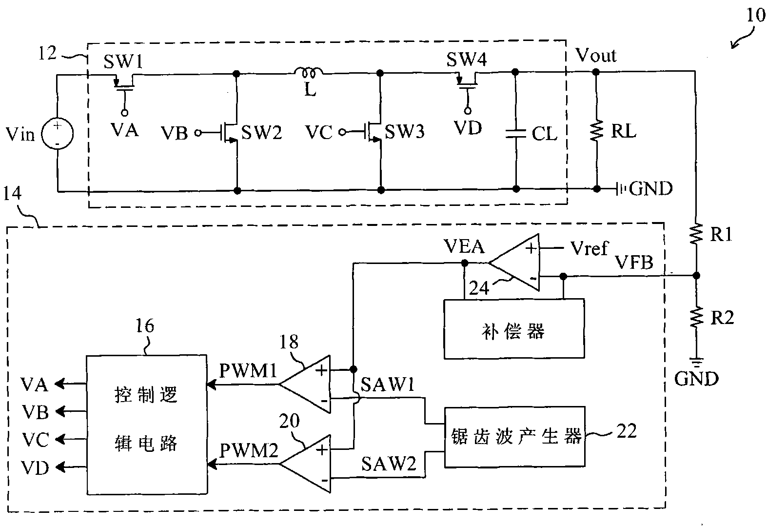
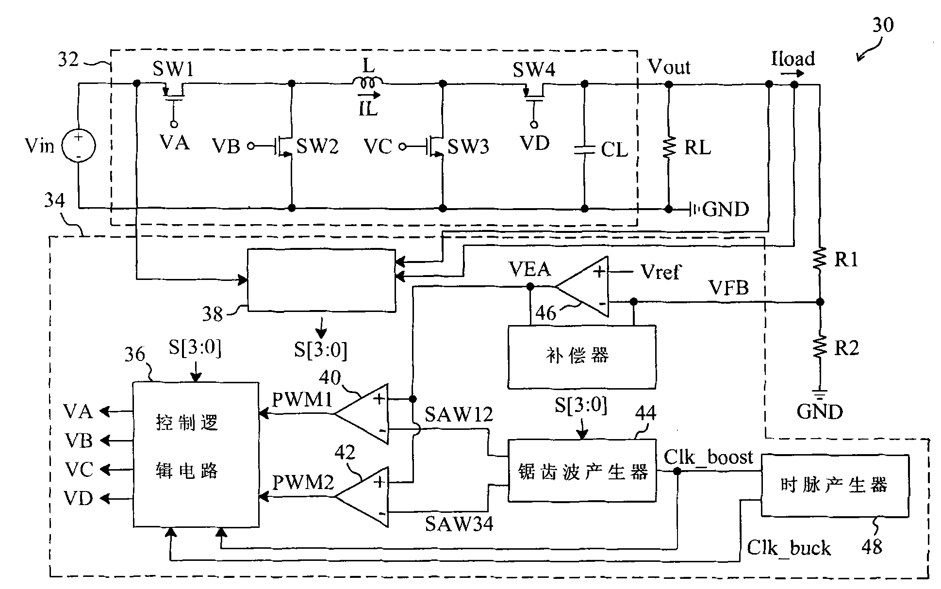
[0222] see now figure 2 , figure 2 A first embodiment of the present invention is shown. As shown in the figure, in the buck-boost power converter 30, the control circuit 34 outputs the control signals VA, VB, VC and VD to drive the power stage 32 to convert the input voltage Vin into the output voltage Vout, the resistors R1 and The output voltage Vout divided by R2 generates a feedback signal VFB to the control circuit 34 . In the power stage 32, the switch SW1 is connected between the input voltage Vin and the inductor L, the switch SW2 is connected between the inductor L and the ground terminal GND, the switch SW3 is connected between the inductor L and the ground terminal GND, and the switch SW4 is connected between the inductor L and the ground terminal GND. between L and the output voltage Vout. Since the duty cycle of the entire system i...


PUM


Abstract

The invention relates to a control method of a boost-buck type power supply converter, and the power supply converter comprises an inductor, a first switch connected between the input end of the power supply converter and the first end of the inductor, a second switch connected between the first end of the inductor and the grounding end, a third switch connected between the second end of the inductor and the grounding end, and a fourth switch connected between the second end of the inductor and the output end of the power supply converter; and the control method is characterized in that the control method comprises the following steps: detecting voltage at the input end and the output end and load current at the output end for deciding whether the power supply converter performs the operation in the buck mode, the first boost-buck mode, the second boost-buck mode or the boost mode; and controlling the first, the second, the third and the fourth switches during the first and the second boost-buck modes.

Description

technical field [0001] The present invention relates to a power converter, in particular, to a buck-boost power converter and a control method thereof which can improve switching loss and correct switching mode. Background technique [0002] figure 1 A known buck-boost power converter 10 is shown, including a power stage 12 and a control circuit 14 . In the power stage 12, the switch SW1 is connected between the input voltage Vin and the inductor L, the switch SW2 is connected between the inductor L and the ground terminal GND, the switch SW3 is connected between the inductor L and the ground terminal GND, and the switch SW4 is connected between the inductor L and the ground terminal GND. between L and the output voltage Vout. The output voltage Vout is divided by the resistors R1 and R2 to generate the feedback signal VFB. In the control circuit 14, the error amplifier 24 generates the error signal VEA according to the feedback signal VFB and the reference voltage Vref, a...

Claims


Application Information

Patent Timeline
Patent Type & Authority Applications(China)
IPC IPC(8): H02M3/158
Inventor 陈科宏吴纬权何心欣
Owner RICHTEK TECH
Why Eureka
Try Eureka