Channel searching device and method for broadcasting receiver

A technology for broadcast receivers and received signal strength, applied in broadcast receiving circuits, electrical components, transmission systems, etc., can solve problems such as large differences in counting results, inaccurate channel frequencies, and inability to accurately reflect signal quality, etc., to achieve fast Effective channel search and improved accuracy

Active Publication Date: 2011-05-11
BEKEN CORP
View PDF4 Cites 11 Cited by
  • Summary
  • Abstract
  • Description
  • Claims
  • Application Information

AI Technical Summary

Problems solved by technology

[0004] A major problem with existing products is that when there is a lot of air noise in the channel, the received signal strength RSSI cannot reflect the strength of the useful signal in the channel
[0005] Another problem with existing products is that when the channel signal is very weak, although the signal-to-noise ratio of the demodulated output is high enough, the signal-to-noise ratio of the intermediate frequency signal may be very poor, so the counting results obtained by intermediate frequency counting cannot be accurate. reflect signal quality
[0006] Another problem with existing products is that after changing channels, the gain from RF to demodulation input is not optimal, and the channel frequency may also be inaccurate, which also affects the accuracy of received signal strength RSSI and IF counting
[0007] Another problem with existing products is that under different frequency offsets, even if the signal-to-noise ratio of the input signal is the same, the counting results of the intermediate frequency counting will vary greatly, resulting in this indicator not being able to accurately and effectively reflect the signal quality of the channel.

Method used


Image

  • Channel searching device and method for broadcasting receiver
  • Channel searching device and method for broadcasting receiver
  • Channel searching device and method for broadcasting receiver

Examples


Embodiment Construction

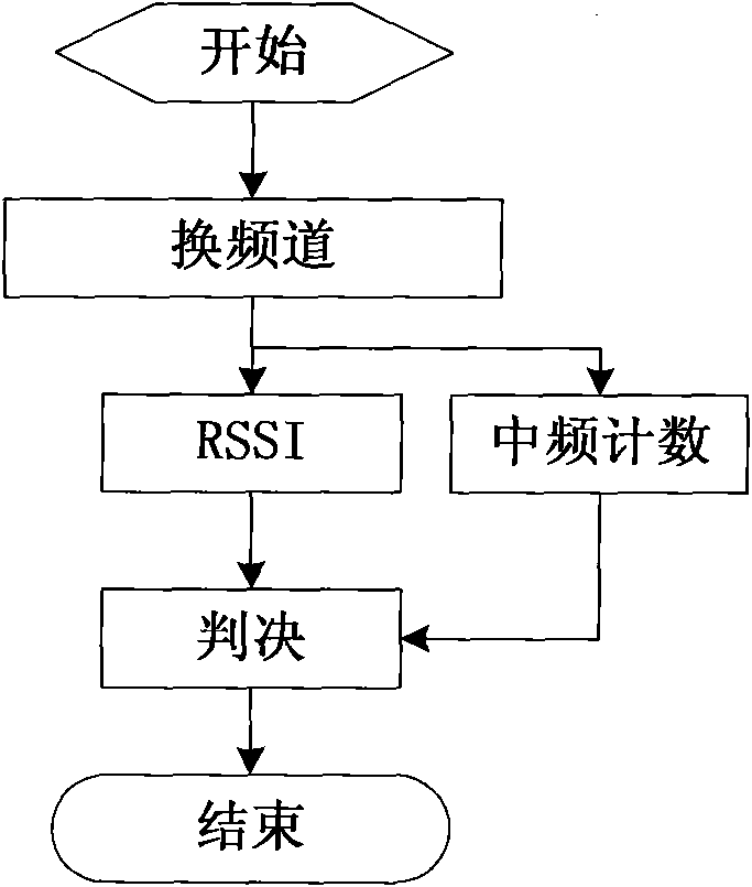
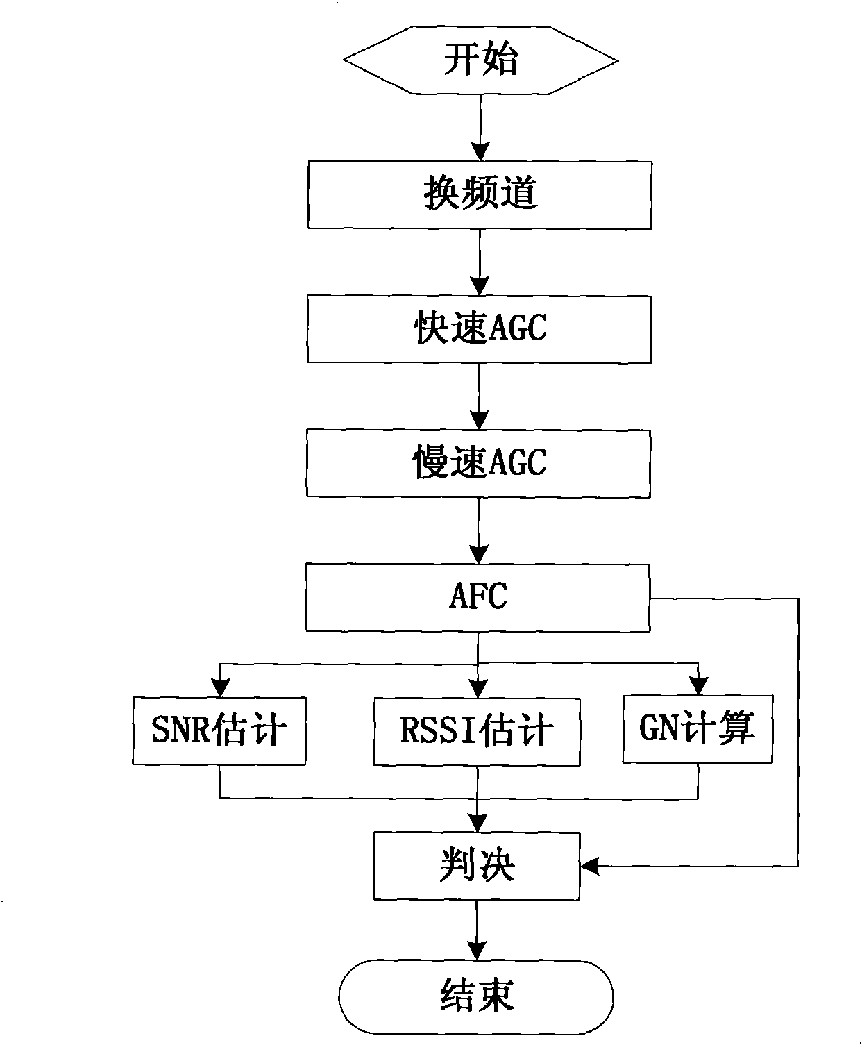
[0021] The main purpose of the present invention is to provide a method and device for channel search in a broadcast receiver. The method first completes automatic gain control (AGC) and automatic frequency control (AFC), and adjusts the front-end gain and receiving frequency to the best value. , And then estimate the received signal strength RSSI and channel quality.

[0022] Another object of the present invention is to provide a more effective channel quality estimation method to estimate the quality of the station. The method estimates the signal-to-noise ratio SNR of the signal in the channel and can be used for FM and AM broadcasting.

[0023] Another purpose of the present invention is to combine the glitches found in the demodulation process to count the number of glitches GN in a certain period, and the number of glitches GN is only used for FM broadcasting.

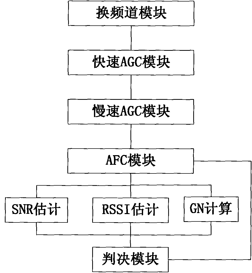
[0024] Such as figure 2 As shown, the main components of the device described in this embodiment include: a channel...


PUM


Abstract

The invention discloses a channel searching device and method for a broadcasting receiver. The channel searching device comprises a channel switching module, an automatic gain control module, an automatic frequency control module, a received signal strength estimation module, a received signal quality estimation module, a demodulated signal quality estimation module and a judgment module, wherein the output end of the channel switching module is connected with the input end of the automatic gain control module; the output end of the automatic gain control module is connected with the input end of the automatic frequency control module; the output end of the automatic frequency control module is connected with the input ends of the received signal strength estimation module, the received signal quality estimation module and the demodulated signal quality estimation module; and the output ends of the received signal strength estimation module, the received signal quality estimation module, the demodulated signal quality estimation module and the automatic frequency control module are connected with the judgment module. The channel searching device and method for a broadcasting receiver can preferably reflect the strength and quality of the wanted signal in a channel and the quality of the demodulated signal, maintain the optimal gains input from radio frequency to demodulation, improve the estimation accuracy on the strength, quality and signal-to-noise ratio of the received signal, improve the estimation accuracy on the number of the quality burrs of the demodulated signal, and realize rapid and effective channel searching.

Description

Technical field [0001] The present invention relates to a communication device and method. The present invention relates to a device and method in a broadcast receiver. Background technique [0002] Broadcast receivers are mainly used to receive FM and AM signals. The station search module is a very important device. Early receivers only used the received signal strength RSSI as a criterion for station quality. This method is suitable for situations where there is no external interference and the noise and interference of each station within the receiver are consistent. However, there are many external interferences in the FM and AM broadcasting bands, and the interference and noise of different channels are also very different, and the performance of the receiver itself on different channels is also different, which requires a better criterion. Recently, many receivers have introduced some criteria related to signal quality. These methods are either only applicable to specific...

Claims


Application Information

Patent Timeline
Patent Type & Authority Applications(China)
IPC IPC(8): H04B1/16H04H40/18
Inventor 王卫锋俞曹刚王吉健
Owner BEKEN CORP
Why Eureka
Try Eureka