Acoustical coupling apparatus

An acoustic coupling and device technology, applied in the direction of sensor parts, sensors, electrical components, etc., can solve the problem of damaging the unbalanced characteristics of the filter, and achieve the goal of eliminating asymmetry, improving amplitude and phase imbalance, and enhancing roll-off characteristics Effect

Active Publication Date: 2011-05-11
ROFS MICROSYST TIANJIN CO LTD
View PDF3 Cites 0 Cited by
  • Summary
  • Abstract
  • Description
  • Claims
  • Application Information

AI Technical Summary

Problems solved by technology

On the other hand, when switching from unbalanced mode to balanced mode, the existence of the decoupling layer capacitance in the CRF greatly damages the unbalanced characteristics of the filter, because it can generate asymmetric capacitance to ground at the balanced output port or feedback capacitor
[0004] Therefore, there is no way to solve the above-mentioned defects and deficiencies so far in this technical field

Method used


Image

  • Acoustical coupling apparatus
  • Acoustical coupling apparatus
  • Acoustical coupling apparatus

Examples


Embodiment Construction

[0058] The acoustic coupling device of the present invention will be described in detail below with reference to the embodiments and the accompanying drawings.

[0059] The invention will be described with reference to the text and drawings, in which some typical examples of the invention are shown. There are many embodiments of this patent, however this patent is not limited to the examples given here. Moreover, these forms are provided to better illustrate and understand the patented technology, and to fully summarize the scope of application of the patent. Like reference symbols designate like structural parts.

[0060] The patent will be described in more detail below with reference to accompanying drawings 1-12.

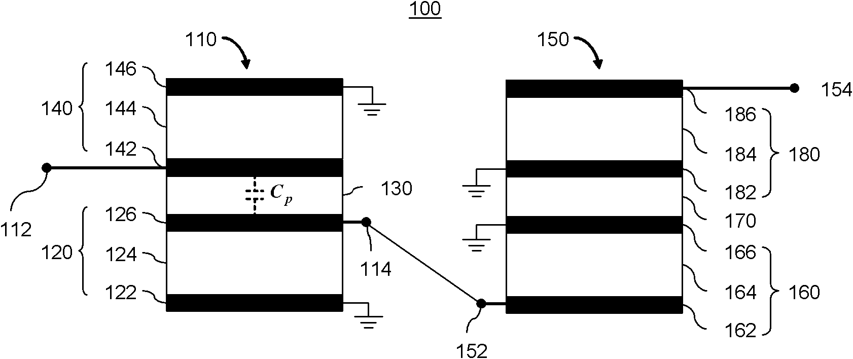
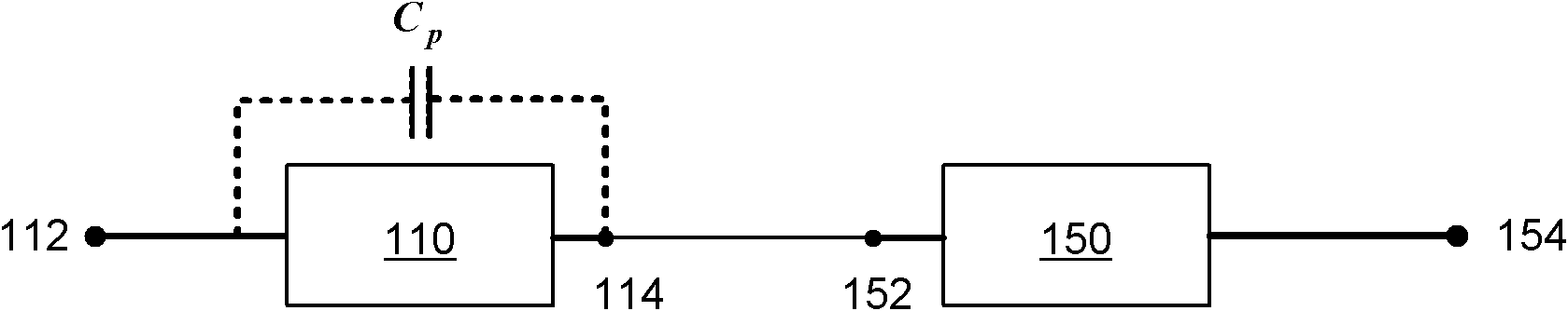
[0061] refer to Figure 1A , shows the first form of the present invention, the structure of the acoustic coupling device 100 . The acoustic coupling device 100 has a first CRF (Coupling Resonance Filter) 110 and a second CRF 150 . The first CRF 110 includes...


PUM


Abstract

The invention provides an acoustical coupling apparatus which comprises a first CRF (coupled resonator filter) and a second CRF electrically coupled with the first CRF, wherein the first CRF and the second CRF are respectively provided with an input port, an output port and a bottom FBAR (film bulk acoustic resonator); an acoustical decoupling layer is formed on each bottom FBAR; a top FBAR is formed on each acoustical decoupling layer; each bottom FBAR and each top FBAR are respectively provided with a bottom electrode; a piezoelectric layer is formed on each bottom electrode; a top electrode is formed on each piezoelectric layer; the input port and output port of each CRF are respectively electrically connected to the corresponding bottom electrodes and the corresponding top electrodes, so as to position the acoustical decoupling layers between the bottom electrodes and the top electrodes; and the output port of the first CRF is electrically connected to the input port of the second CRF. According to the invention, a capacitor which is composed of the decoupling layer in a coupled resonator filter and upper and lower electrodes is utilized, the roll-off performance of the filter is greatly enhanced on the premise of not adding any extra processing step.

Description

technical field [0001] The invention relates to an acoustic coupling device. In particular, it relates to an acoustic device composed of two coupled resonant filters connected in series. Background technique [0002] Bulk acoustic wave (BAW) resonators typically consist of two metal electrodes with a piezoelectric material sandwiched between them. When an alternating voltage is applied between the two electrodes, the electric field between the two electrodes interacts with the piezoelectric material to create sound waves inside the piezoelectric material. The resonant frequency of a BAW device depends on many factors, but the thickness of the piezoelectric layer is the dominant factor in determining the resonant frequency. Fundamental resonance occurs when the wavelength of the stimulated mechanical wave is twice the thickness of the piezoelectric layer. The resonance frequency increases as the thickness of the piezoelectric layer decreases. The resonant frequency of the...

Claims


Application Information

Patent Timeline
Patent Type & Authority Applications(China)
IPC IPC(8): H04R1/00H04R3/00
Inventor 张浩庞慰周冲
Owner ROFS MICROSYST TIANJIN CO LTD
Why Eureka
Try Eureka