Fan-shaped grater for foodstuffs

A friction device, fan-shaped technology, applied in the direction of applications, home appliances, kitchen appliances, etc., to avoid bending and improve the effect of stable positioning

Inactive Publication Date: 2011-05-11
EMSA
View PDF4 Cites 2 Cited by
  • Summary
  • Abstract
  • Description
  • Claims
  • Application Information

AI Technical Summary

Problems solved by technology

Another disadvantage is that different friction devices are required, which are stored and removed separately depending on how thick or thin the disintegration should be

Method used


Image

  • Fan-shaped grater for foodstuffs
  • Fan-shaped grater for foodstuffs
  • Fan-shaped grater for foodstuffs

Examples


Embodiment Construction

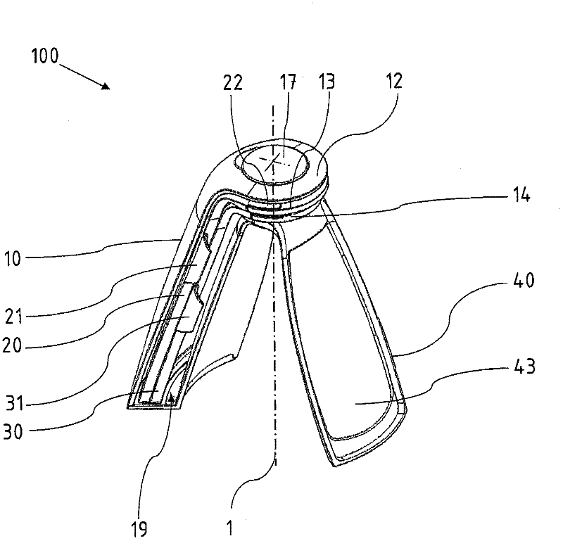
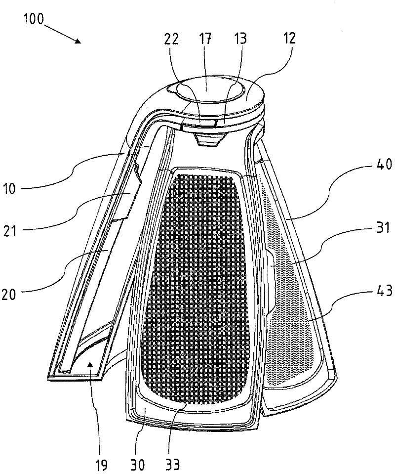
[0030] exist figure 1 100 shows a fan-shaped friction device 100 , which comprises an outer base element 10 which is curved in its upper region and merges into a head region 12 .

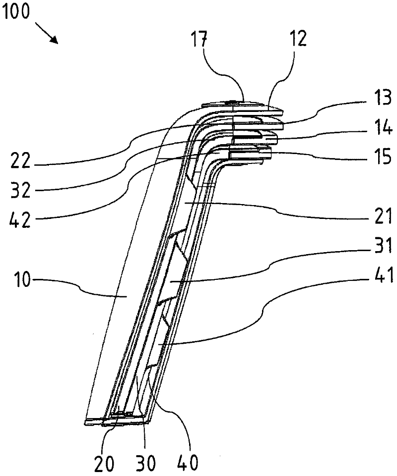
[0031] In the head region 22 of the first friction block 20 is formed a specially shaped head part 13 which, in the exemplary embodiment shown, has a non-visible receiving recess so that the pivot element 17 can be inserted there. A pivoting movement about the pivot axis 1 is thus achieved.

[0032] Below the head part 13 there is a further head part 14 for the second friction brake module 30 . The third friction block 40 is swiveled out and opposite the base element 10 , thus creating a parabolic profile and the fan-shaped friction block is free standing. The friction modules 20 and 30 remain in the receiving chamber 19 in the hollow base element 10 and can be swiveled out of the base element 10 by means of their grip tabs 21 , 31 . In the storage state, the friction modules 20 , 30 , 40 are thu...


PUM


Abstract

A fan-shaped grater (100) for foodstuffs comprises at least one base element (10) and at least one grater module (20, 30, 40). The base element (10) and grater module (20, 30, 40) therein are each curved, angled or cropped and run out into a head region (12, 22, 32, 42). A common pivot axis (1) runs through the head region (12, 22, 32, 42). By fanning out the grater modules (20, 30, 40) with respect to the base element (10), a parabola-shaped configuration is formed so that the fan-shaped grater (100) can stand independently and the grating surface (43) is positioned at a slant to the vertical pivot axis (1).

Description

technical field [0001] The invention relates to a fan-shaped grater for food, which comprises at least one basic element and at least one grater module, the basic element and the grater module are respectively arc-shaped curved, bent or bent and ends in the head region. Background technique [0002] Some hand grates are known for breaking down food. They have a generally metallic friction surface with openings on which protruding cutting edges are formed. If the item to be cut is guided along the friction surface, parts of the item to be cut are cut off by the blade and discharged through the opening. In this case, conventional household frictions usually have a gripping element and, at the opposite end, a foot element, in particular an elastomeric foot element, which presses the friction device with its lower edge to the Creates some slip resistance against the foundation when on the mat. [0003] However, a disadvantage of the known friction device is that, in order t...

Claims


Application Information

Patent Timeline
Patent Type & Authority Applications(China)
IPC IPC(8): A47J43/25
CPCA47J43/25
Inventor N·阿梅莉P·布德
Owner EMSA
Why Eureka
Try Eureka