Supercharge Your Innovation With Domain-Expert AI Agents!

Photovoltaic cell, and substrate for same

A technology for photovoltaic cells and substrates, applied in photovoltaic power generation, circuits, electrical components, etc., can solve problems such as difficult deposition

Inactive Publication Date: 2011-05-11
SAINT-GOBAIN GLASS FRANCE
View PDF1 Cites 1 Cited by
  • Summary
  • Abstract
  • Description
  • Claims
  • Application Information

AI Technical Summary

Problems solved by technology

This layer also has the disadvantage of being very difficult to deposit by magnetron sputtering techniques, where objects incorporating this material are electrically insulating in nature

Method used


Image

  • Photovoltaic cell, and substrate for same
  • Photovoltaic cell, and substrate for same
  • Photovoltaic cell, and substrate for same

Examples


Embodiment Construction

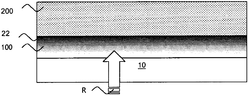
[0046] figure 1 Illustrated is a photovoltaic cell panel substrate 10 according to the invention having an absorbing photovoltaic material 200 with a transparent electrode coating 100 consisting of TCO on a major surface, said The transparent electrode coating 100 is also referred to as transparent conductive layer.

[0047] The panel substrate 10 is arranged in the photovoltaic cell in such a way that the panel substrate 10 is the first substrate through which incident radiation R passes before reaching the photovoltaic material 200 .

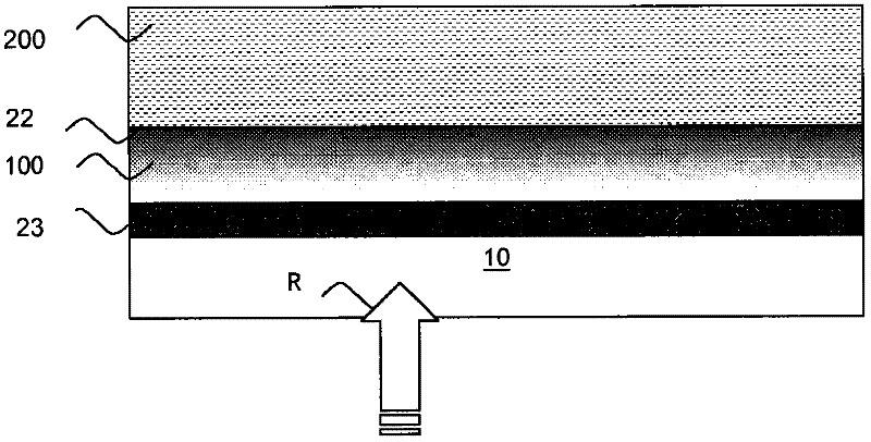
[0048] figure 2 and figure 1 The difference lies in the fact that a bonding layer 23 is interposed between the conductive layer 100 and the substrate 10 .

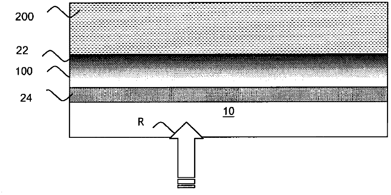
[0049] image 3 and figure 1 The difference lies in the fact that an alkali metal barrier layer 24 is interposed between the conductive layer 100 and the substrate 10 .

[0050] Figure 4 merged into figure 2 and image 3 The setup of the solution given in , incorporates the fac...


PUM

PropertyMeasurementUnit
thicknessaaaaaaaaaa
thicknessaaaaaaaaaa
thicknessaaaaaaaaaa

Abstract

The invention relates to a method for manufacturing an optionally doped transparent zinc oxide electrode, characterized in that a zinc oxide layer is deposited on at least one of the surfaces of a substrate or at least one layer in contact with one of the surfaces of said substrate, and in that said layer is subjected to a controlled oxidation to overoxidize a surface portion of said layer on a fraction of the body thereof.

Description

technical field [0001] The present invention relates to a photovoltaic cell panel substrate, in particular to a transparent glass substrate, and to a photovoltaic cell incorporating such a substrate. Background technique [0002] In a photovoltaic cell, a photovoltaic system with a photovoltaic material that generates electricity by the effect of incident radiation is placed between a base substrate and a panel substrate, where this panel substrate is the first pass through which the incident radiation passes before reaching the photovoltaic material. a substrate. [0003] In this photovoltaic cell, the panel substrate typically has a transparent electrode beneath the major surface facing the photovoltaic material that is in electrical contact with the underlying photovoltaic material when the main direction of arrival of the incident radiation is considered to be via the top coating. [0004] This panel electrode coating thus usually constitutes the negative terminal (or ...

Claims


Application Information

Patent Timeline
Patent Type & Authority Applications(China)
IPC IPC(8): H01L31/0224H01L31/18
CPCC03C17/245C03C17/36C03C17/3678C03C2217/216C03C2217/944H01L31/1884Y02E10/50
Inventor E·彼得
Owner SAINT-GOBAIN GLASS FRANCE
Features
  • R&D
  • Intellectual Property
  • Life Sciences
  • Materials
  • Tech Scout
  • Unparalleled Data Quality
  • Higher Quality Content
  • 60% Fewer Hallucinations
Learn More