Catalyst crushing and absorbing device of tubular reactor

A tubular reactor and catalyst technology, applied in chemical/physical processes, chemical instruments and methods, etc., can solve the problems of catalyst hardening, speeding up the unloading time, catalyst hardening and breaking, etc., so as to reduce the difficulty of unloading and speed up the unloading. time, the effect of shortening the removal time

Active Publication Date: 2013-02-27
JIANGSU TIANPENG PETROCHEMICAL TECH CO LTD
View PDF1 Cites 0 Cited by
  • Summary
  • Abstract
  • Description
  • Claims
  • Application Information

AI Technical Summary

Problems solved by technology

[0006] Aiming at the problem of catalyst hardening during the unloading of the existing tubular reactor, the present invention designs a novel catalyst crushing and suction device for the tubular reactor, which can not only improve the unloading efficiency of the catalyst, speed up the unloading time, but also eliminate The problem of dust pollution when unloading the agent can completely solve the problem of severe hardening and breaking of the catalyst.

Method used


Image

  • Catalyst crushing and absorbing device of tubular reactor

Examples


Embodiment 1

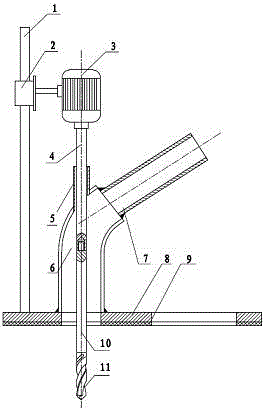
[0017] Embodiment 1: as figure 1 As shown, a catalyst crushing and unloading device for a tubular reactor, the device is supported by a base 8, the base 8 is provided with a base bend 6, one end of the base bend 6 communicates with the base 8, and at the mouth of the base bend 6 A suction nozzle 7 is arranged at the place, and the base elbow 6 and the suction nozzle 7 are sealed and connected; near the mouth of the base elbow 6, an extension rod fixing sleeve 5 for the passage of the electric mashing device is provided, and The electric crushing device and the extension rod fixing sleeve 5 are in a sealed state; the electric crushing device is fixed by the support rod 1 .

Embodiment 2

[0018] Embodiment 2: as figure 1 As shown, a tubular reactor catalyst crushing and unloading device, the device is supported by a base 8, the base 8 is provided with a base bend 6, the base bend 6 communicates with the base 8, and at the mouth of the base bend 6 A suction nozzle 7 is provided, the base elbow 6 and the suction nozzle 7 are fixedly connected by a gasket, and are in a sealed state, and an extension rod is provided at the nozzle close to the base elbow 6 for the passage of the electric mashing device The sleeve 5 is fixed, and the electric mashing device and the extension rod fixing sleeve 5 are in a sealed state; the electric mashing device is fixed by the support rod 1 .

[0019] Electric smashing device is made up of motor 3, the rod that links to each other with motor 3 and the drill bit 11 that is arranged on the rod top. The bar that links to each other with motor 3 is movable rod, and movable rod is extension rod 4,10, is to be connected by screw thread be...

Embodiment 3

[0020] Embodiment 3: as figure 1 Shown, a kind of tubular reactor catalyst crushing and unloading device, this device is supported by base 8, and this base 8 is provided with base elbow 6, and one end of base elbow 6 communicates with base 8, and at base elbow The other end of 6, that is, the mouth of the nozzle is provided with a suction nozzle 7, the base elbow 6 and the suction nozzle 7 are fixedly connected through a gasket, and are in a sealed state. The suction nozzle 7 is used to pass the vacuum suction machine through Pipeline is connected on the suction nozzle 7 of this device.

[0021] Near the mouth of the base elbow 6 is provided with an extension rod fixed sleeve 5 that can pass through the electric mashing device, and the electric mash device and the extension rod fixed sleeve 5 are in a sealed state; the electric mash device is powered by a motor 3. The rod connected with the motor 3 is composed of the drill bit 11 arranged on the top of the rod. The bar that ...


PUM


Abstract

The invention discloses a catalyst crushing and absorbing device for a tubular reactor, which relates to the catalyst discharging and crushing device of a tubular reactor in the chemical industry and the petrochemical industry. The catalyst crushing and absorbing device is supported by a base (8), a base elbow (6) is arranged on and communicated with the base (8), the port of the base elbow (6) is provided with an absorption pipe head (7), and the base elbow (6) is connected with the absorption pipe head (7) in a sealing mode. A lengthened bar fixed cashing pipe (5) through which an electric crushing device can pass is arranged next to the port of the base elbow (6), the electric crushing device and the lengthening bar fixation cashing pipe (5) are in the sealing status, and the electric crushing device is fixed by a support bar (1). The catalyst crushing and absorbing device of a tubular reactor completely solves the crushing problem of a serious hardened catalyst, lowers difficulty of catalyst discharging, and shortens catalyst discharging time. The catalyst crushing and absorbing device of a tubular reactor is provided with a unique lengthening bar fixation cashing pipe.

Description

technical field [0001] The invention relates to the technical field of catalyst unloading for tubular reactors in the chemical industry and the petrochemical industry, in particular to a catalyst crushing device. Background technique [0002] Many chemical reactors are fabricated as shell and tube heat exchangers with many parallel, vertical tubes extending from a top tube sheet to a bottom tube sheet. During use, the tubes typically contain catalyst, and periodically the reactor must be shut down, the catalyst removed, the tubes cleaned, and fresh catalyst loaded. Difficulties are often encountered during the unloading process. When replacing the catalyst, the general method is to use a metal rod or a rod made of other materials to vibrate upwards from the lower opening of the reactor to make the catalyst inside the reactor tube fall down. All or some of the tubes in the reactor, due to thermal changes or composition changes during the operation, the catalyst in the tubes...

Claims


Application Information

Patent Timeline
Patent Type & Authority Patents(China)
IPC IPC(8): B01J8/06
Inventor 冯永康巩增强
Owner JIANGSU TIANPENG PETROCHEMICAL TECH CO LTD
Why Eureka
Try Eureka