Light-guiding plate and printing method thereof and backlight module

A printing method and technology of a light guide plate, applied in printing, printing machines, rotary printing machines, etc., can solve the problems of increasing printing costs and not allowing them, and achieve the effect of overcoming high printing costs

Active Publication Date: 2011-05-18
BOE TECH GRP CO LTD +1
View PDF0 Cites 39 Cited by
  • Summary
  • Abstract
  • Description
  • Claims
  • Application Information

AI Technical Summary

Problems solved by technology

[0005] In the process of realizing the present invention, the inventors found that there are at least the following problems in the prior art: now, the general light guide plate is printed and formed at one time. printing machine, the cost is more than 5 times that of the existing printing machine
Therefore, the use of full-page printing for the light guide plate increases the printing cost, especially in the early development stage of the product, and this kind of cost investment is not allowed

Method used


Image

  • Light-guiding plate and printing method thereof and backlight module
  • Light-guiding plate and printing method thereof and backlight module
  • Light-guiding plate and printing method thereof and backlight module

Examples


Embodiment 1

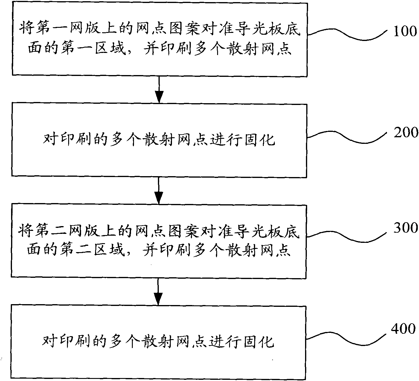
[0051] figure 2 The flow chart of the printing method of the light guide plate provided by Embodiment 1 of the present invention adopts screen printing technology, and the specific steps include:

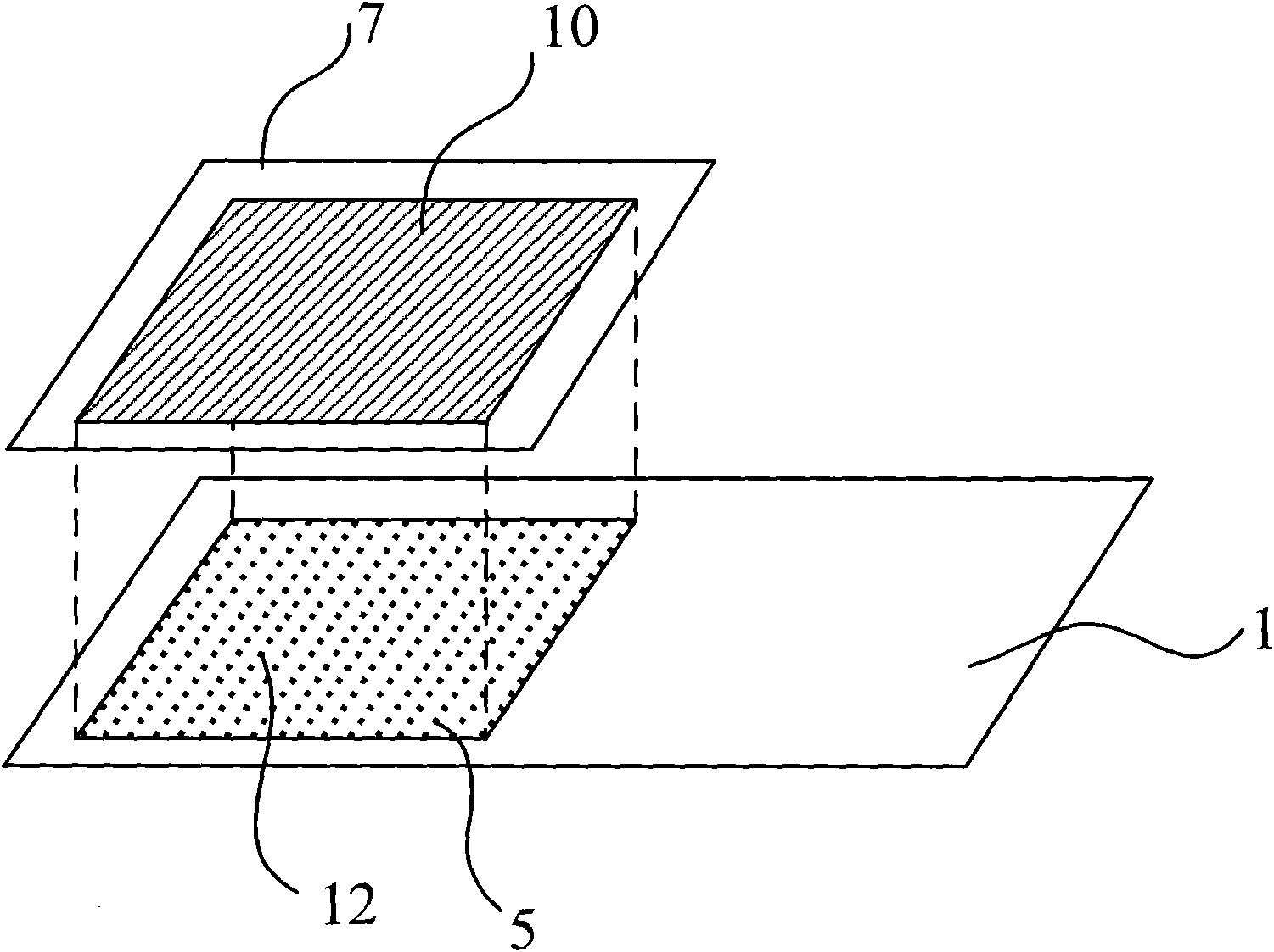
[0052] Step 100, align the dot pattern 10 on the first screen 7 with the first area 12 on the bottom surface of the light guide plate 1, and print a plurality of scattering dots 5, such as image 3 As shown, it is preferred to make the upper edge, lower edge and left edge of the dot pattern 10 parallel to the upper edge, lower edge and left edge of the light guide plate 1 and have the same distance;

[0053] Step 200, curing the printed plurality of scattering dots 5;

[0054] Step 300, align the dot pattern 10 on the second screen 8 with the second area 13 on the bottom surface of the light guide plate 1, and print a plurality of scattering dots 5 to form a stitching area 14 between the first area 12 and the second area 13 ,Such as Figure 4 As shown, it is preferable to make t...

Embodiment 2

[0065] Figure 8 The structure schematic diagram of the light guide plate provided by Embodiment 2 of the present invention, the light guide plate 1 is printed with a plurality of scattering dots 5 on the bottom surface by screen printing technology, and the function of the scattering dots 5 is that when the light hits each scattering dot 5 , the reflected light will diffuse to various angles, and then destroy the reflection condition and be evenly emitted from the light guide plate 1 . The above-mentioned light guide plate 1, by screen printing, a plurality of scattering dots 5 are respectively formed in at least the first area 12 and the second area 13 adjacent to the first area of ​​the bottom surface of the light guide plate 1, between two adjacent areas A splice region 14 is formed, as Figure 8 As shown, the shape of the stitching area 14 is a straight line, and in specific applications, the shape of the stitching area 14 can also be a zigzag line or a circular arc line...

Embodiment 3

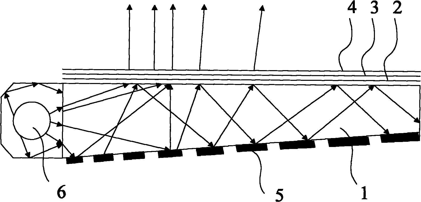
[0070] Figure 10 The structure schematic diagram of the backlight module provided by Embodiment 3 of the present invention, the backlight module of this embodiment includes: a light guide plate 1, a diffuser plate 2 arranged on the upper surface of the light guide plate 1, and a diffuser plate arranged on the upper surface of the diffuser plate 2 The prism sheet 3 , the light source 6 located on one side of the light guide plate 1 and the reflection plate 17 located on the bottom surface of the light guide plate 1 .

[0071] The bottom surface of the light guide plate 1 is printed with a plurality of scattering dots 5, and the scattering dots 5 are respectively formed in at least the first area 12 and the second area 13 adjacent to the first area on the bottom surface of the light guide plate 1, and between the two adjacent areas A stitching region 14 is formed between them. The backlight module can adopt the light guide plate 1 provided by any one of the foregoing embodimen...


PUM


Abstract

The invention relates to a light-guiding plate and a printing method thereof and a backlight module. The printing method comprises the following steps of: printing a plurality of scattering screen dots in a first region at the bottom surface of the light-guiding plate by using a first screen printing plate and adopting a screen printing technology; solidifying the plurality of printed scattering screen dots; printing a plurality of scattering screen dots in a second region of the bottom surface of the light-guiding plate by using a second screen printing plate to form a splicing zone between the first region and the second region; and solidifying the plurality of printed scattering screen dots. The backlight module comprises a light-guiding plate, a diffusing plate, a prism sheet, a light source and a reflecting plate. The bottom surface of the light guide plate is printed with a plurality of scattering screen dots, wherein the scattering screen dots are respectively at least formed in the first region and the second region adjacent to the first region, and the splicing zone is formed between two adjacent printing regions. By adopting the splicing printing technology, the printing cost of the large-scale light-guiding plate can be reduced, and the large-size light-guiding plate and the backlight module are obtained.

Description

technical field [0001] The invention relates to a backlight module technology of a liquid crystal display device, in particular to a light guide plate, a printing method thereof and a backlight module. Background technique [0002] At present, in the flat panel display technology, the liquid crystal display occupies a dominant position, and the transmissive liquid crystal display is the mainstream of the current liquid crystal display technology. Since the LCD itself does not emit light, a backlight module is essential for a transmissive LCD. In general, backlight modules can be divided into edge-lit and direct-lit. At present, edge-lit backlight modules are mainly used in liquid crystal displays, while direct-lit backlight modules are mainly used in LCD TVs. [0003] Now TVs are developing toward Light Emitting Diode (hereinafter referred to as LED) and ultra-thin, but direct-lit backlight modules cannot meet the technical requirements in this area, so edge-lit backlight ...

Claims


Application Information

Patent Timeline
Patent Type & Authority Applications(China)
IPC IPC(8): B41M1/12B41F15/34F21V8/00F21V13/00G02F1/13357
Inventor 刘飞杨东升
Owner BOE TECH GRP CO LTD
Why Eureka
Try Eureka