Suspension unit structure of maglev train

A maglev train and unit structure technology, applied in electric vehicles, vehicle components, electric traction, etc., can solve problems such as increasing the manufacturing, installation and maintenance costs of guide rails and beams, increasing the difficulty of controller design, and affecting the stability of the suspension system. , to reduce design difficulty, improve dynamic characteristics, and facilitate production and processing.

Inactive Publication Date: 2011-05-18
SOUTHWEST JIAOTONG UNIV
View PDF4 Cites 14 Cited by
  • Summary
  • Abstract
  • Description
  • Claims
  • Application Information

AI Technical Summary

Problems solved by technology

[0005] Since the maglev train adopts multi-point suspension control technology, the coupling caused by the characteristics of the mechanical structure will inevitably lead to the mutual coupling between the various suspension controllers, which will affect the stability of the suspension system of the vehicle.
The commonly used processing method is to regard this coupling as the external disturbance of the system, and suppress it by improving the robustness of the system, which makes the design of the controller more difficult
Moreover, the suspension, guiding and driving systems put forward higher design and manufacturing accuracy requirements for the three functional surfaces of the guide rail. The manufacturing and installation accuracy requirements are basically within 1 mm, which increases the manufacturing, installation and maintenance costs of the guide rail and beam.

Method used


Image

  • Suspension unit structure of maglev train
  • Suspension unit structure of maglev train
  • Suspension unit structure of maglev train

Examples


Embodiment Construction

[0013] The present invention will be further described below in conjunction with accompanying drawing.

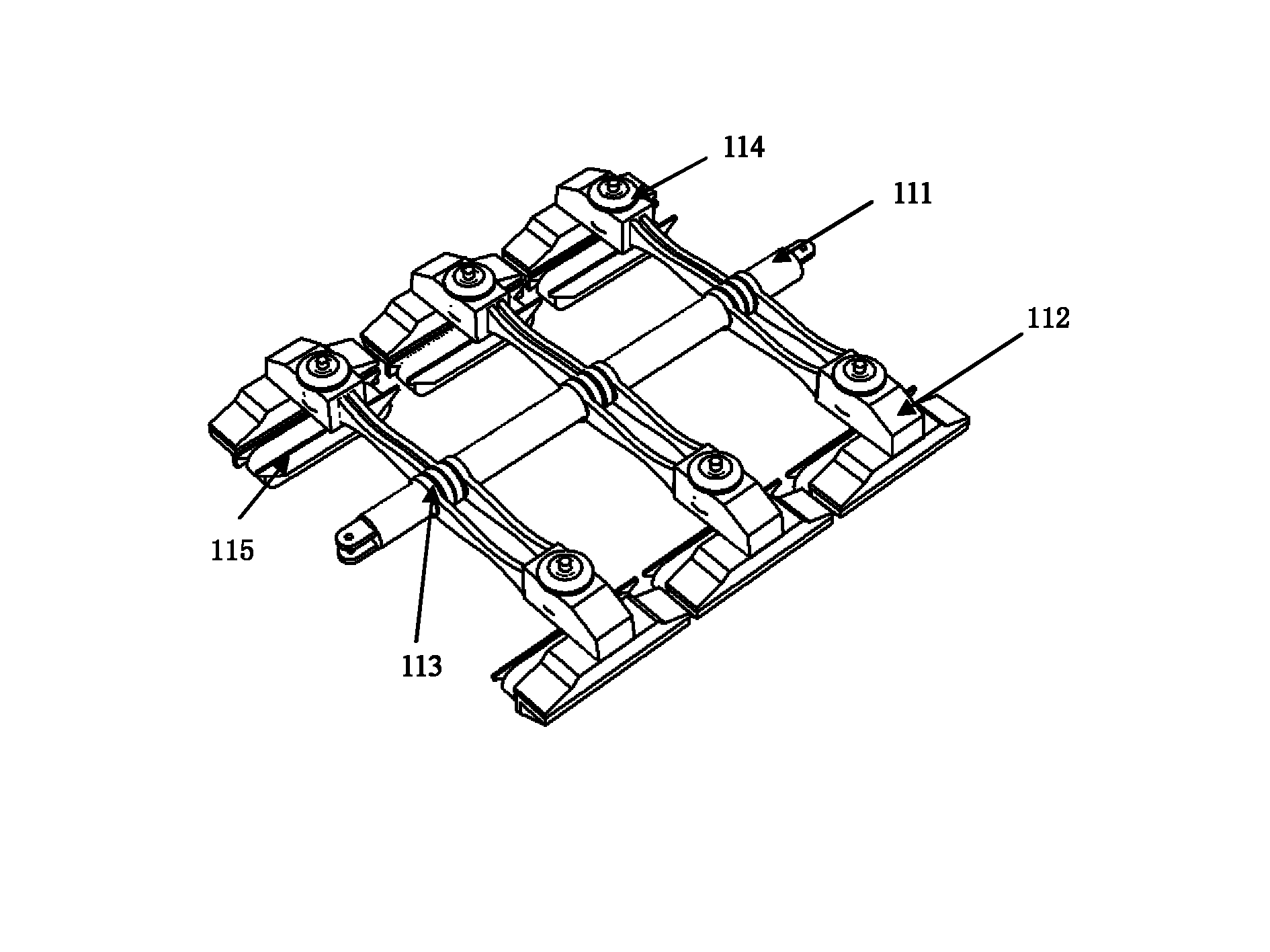
[0014] exist image 3 Middle: the suspension frame has a longitudinal support beam 111 fixed in the middle of the car body of the maglev train. One end of the suspension guide module is sleeved on the support beam 111 through the bearing 113, and the suspension guide modules are symmetrically arranged on both sides of the longitudinal support beam in pairs. The suspension guide module is composed of a transverse support 112 and an electromagnet 115 arranged at one end of the transverse support. The suspension guide module is provided with an air spring 114 for coupling with the vehicle body.

[0015] In one bogie unit, at least two pairs of suspension guide modules are sleeved on the longitudinal support beam 111 . In this embodiment, three pairs of suspension guide modules are socketed as an example.

[0016] What is stated above is only the preferred implementation of ...


PUM


Abstract

The invention discloses a suspension unit structure of a maglev train. A suspension frame is provided with a longitudinal supporting beam fixed at the middle part of the body of the maglev train; one ends of suspension guide modules are sleeved on the supporting beam through bearings and are pairwise arranged at two sides of the longitudinal supporting beam in bilateral symmetry, each suspension guide module consists of a cross bracket and an electric magnet arranged at one end of the bracket, and air springs used for connecting with the body of the maglev train are arranged on the suspension guide modules. In the suspended unit structure, a suspension controller of each module can be designed as an independent system, thereby reducing the design difficulty of the controllers, improving the stability of a suspension system and dynamic operating characteristics of the maglev train, and further reducing design and manufacturing precision requirements of a low guide rail functional plane and the comprehensive cost.

Description

technical field [0001] The invention relates to maglev trains, especially to the field of equipment manufacturing of conventional (EMS type) maglev trains. Background technique [0002] The constant conduction maglev train (EMS type) uses the electromagnetic attraction of ordinary DC electromagnets to make the train float, and is driven by a linear motor without contact. It is divided into high-speed type and low-speed type. The low-speed type is represented by Japan's HSST, while the high-speed type is represented by the German TR series. [0003] The low-speed EMS maglev train is jointly suspended by multiple longitudinal magnetic bogies connected end to end, and each bogie is as figure 1 shown. All have independent suspension, guidance and drive functions. The bogie and the vehicle body are connected by an air spring 1 . Each bogie is composed of two relatively independent modules 3 connected by anti-roll beams 2 . Since the modules on both sides of the bogie are con...

Claims


Application Information

Patent Timeline
Patent Type & Authority Applications(China)
IPC IPC(8): B60L13/04
Inventor 蒋启龙赵国明
Owner SOUTHWEST JIAOTONG UNIV
Why Eureka
Try Eureka