Brake for railway vehicle unit

A rail vehicle and brake technology, which is applied to the operating mechanism of the brake of the railway vehicle, the brake wear compensation mechanism, the railway braking system, etc., can solve the problems of weakening the braking effect, slow stroke adjustment, low transmission efficiency, etc. Uniform, space-saving, small volume effect

Active Publication Date: 2011-05-18
CRRC QINGDAO SIFANG ROLLING STOCK RES INST
View PDF6 Cites 16 Cited by
  • Summary
  • Abstract
  • Description
  • Claims
  • Application Information

AI Technical Summary

Problems solved by technology

Existing railway vehicles generally use two-way brake shoe clearance adjusters. However, not only the structure is complex, but also the stroke adjustment is slow. Generally, three braking and relief are required to complete all clearance adjustments. The transmission efficiency is low and the braking effect is weakened. , poor safety performance

Method used


Image

  • Brake for railway vehicle unit
  • Brake for railway vehicle unit
  • Brake for railway vehicle unit

Examples


specific Embodiment approach

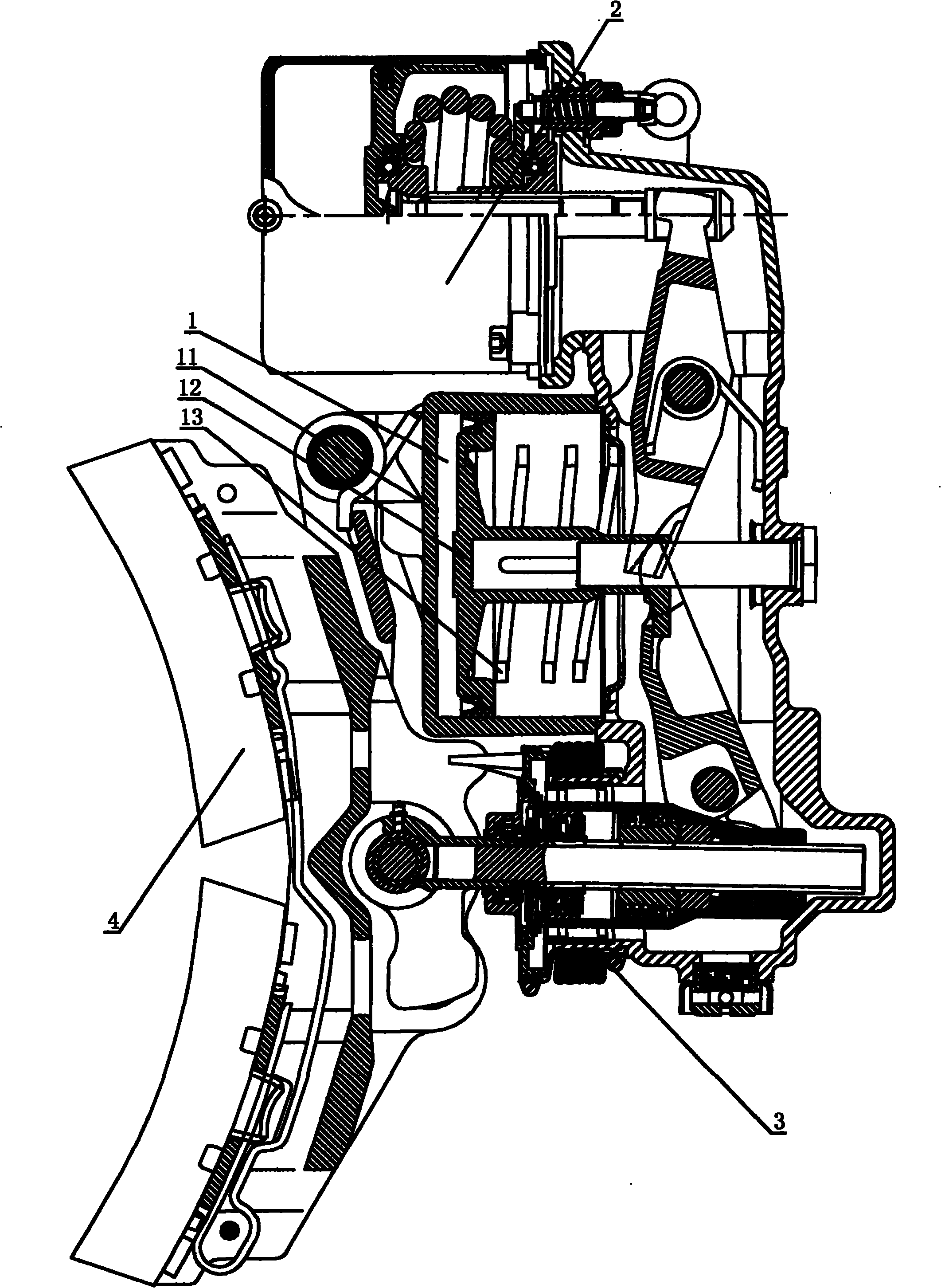
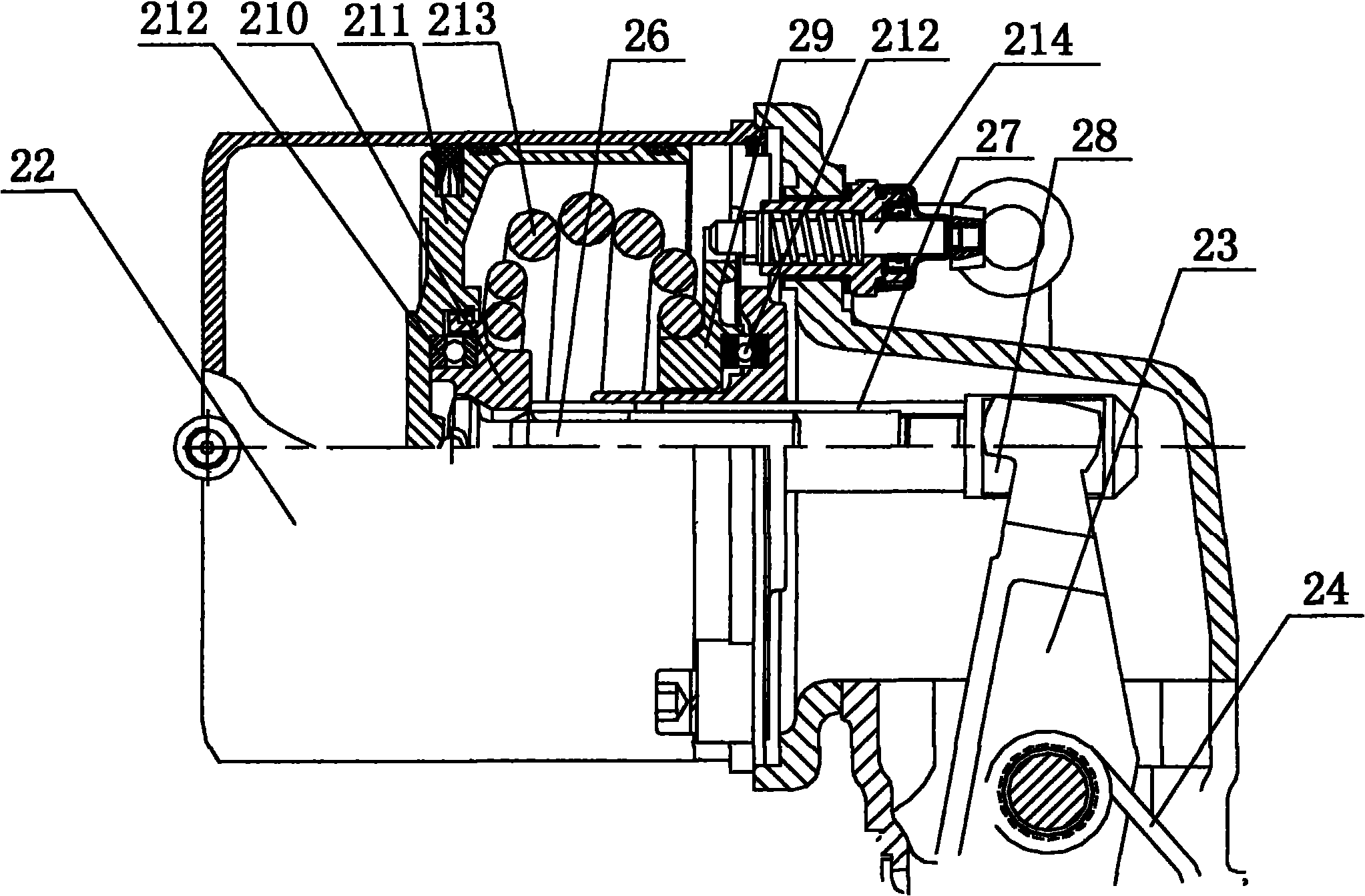
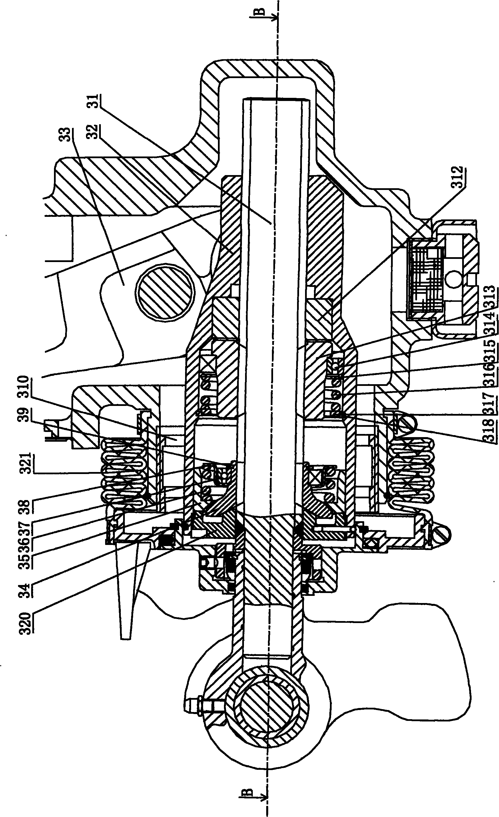
[0019]A rail vehicle unit brake, provided with a brake box, a brake release device 1 located on the brake box, a spring parking device 2, a brake shoe wear gap compensation adjustment device 3, and a brake shoe component 4 located in the brake shoe wear gap The end of the compensation adjustment device 3, the brake relief device includes a brake cylinder 11, the brake lever 12 of the brake cylinder 11 is linked with the brake lever 33 and the spring parking lever 23, and the end of the brake lever 33 Cooperate with the brake shoe wear gap compensation adjustment device, the spring parking lever 23 cooperates with the spring parking device; the spring parking device includes a spring cylinder 22 arranged on the brake box, and the power of the spring cylinder 22 The spring parking lever 23 connected by the output rod, the spring parking lever 23 is axially connected to the brake box, and a torsion spring 24 is arranged between the spring parking lever 23 and the brake box. During...


PUM


Abstract

The invention relates to a brake for a railway vehicle unit, which is provided with a brake box body, a brake release device (1) located on the brake box body, a spring stopping device (2) and a brake-shoe abrasion backlash compensation adjuster (3). A brake-shoe assembly (4) is located at the end part of the brake-shoe abrasion backlash compensation adjuster (3). The invention has the advantagesof simple integral structure, reasonable design, space saving, small volume, convenience for installation, uniform force and firm and wearable force propagation path segment. The brake release deviceis used for adjusting the brake-shoe directly via the brake-shoe abrasion backlash compensation adjuster and the spring stopping device can directly control the brake-shoe assembly via a spring stopping lever and the brake-shoe abrasion backlash compensation adjuster.

Description

technical field [0001] The invention relates to a railway vehicle unit brake, in particular to a railway vehicle unit brake integrating brake relief, brake shoe wear gap compensation adjustment and spring parking brake. Background technique [0002] As a basic braking device, the unit brake is widely used in railway locomotives, subways and other rail transit vehicles. It is the final executive component of the braking system, and it acts on the vehicle tread and is the direct applicator of the braking force. However, existing unit brakes have common disadvantages. In rail vehicle unit brakes, due to space constraints, the size of the brake cylinder is fixed, so the limit space of the brake stroke is small, and ordinary springs are used. The wire is a circular spring, and its force cannot meet the requirements of relief. After increasing the diameter of the spring wire, although the relief force is increased, the spring takes up a lot of space after pressing and does not mee...

Claims


Application Information

Patent Timeline
Patent Type & Authority Applications(China)
IPC IPC(8): B61H13/20B61H15/00
Inventor 宋传云孔德鹏王广凯李培署欧阳省
Owner CRRC QINGDAO SIFANG ROLLING STOCK RES INST
Why Eureka
Try Eureka