Directional antenna and automatic adjustment method thereof

A technology of directional antenna and adjustment unit, applied in the directions of antenna, antenna parts, electrical components, etc., can solve the problem of inconvenient adjustment of directional antenna, and achieve the effect of overcoming the inconvenience of manual adjustment, achieving the best gain, and being easy to adjust.

Inactive Publication Date: 2011-05-18
HUAWEI TECH CO LTD
View PDF3 Cites 6 Cited by
  • Summary
  • Abstract
  • Description
  • Claims
  • Application Information

AI Technical Summary

Problems solved by technology

[0007] The embodiment of the present invention provides a directional antenna and its automatic adjustment method, which is used to solve the problem of inconvenient adjustment of the directional antenna in the prior art and realize the automatic adjustment of the directional antenna

Method used


Image

  • Directional antenna and automatic adjustment method thereof
  • Directional antenna and automatic adjustment method thereof
  • Directional antenna and automatic adjustment method thereof

Examples


Embodiment 1

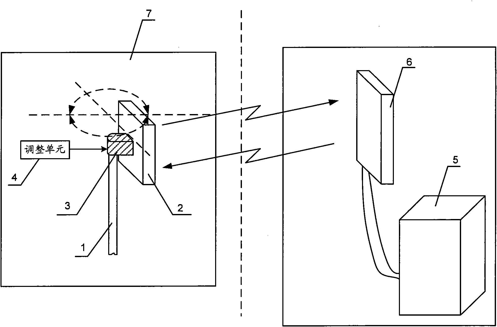
[0027] In Embodiment 1, the directional antenna can also include a mounting bracket 1, and the signal receiving unit 2 can pass through the connecting piece ( figure 1 Not shown in ) is connected with the mounting frame 1.

[0028] In order to facilitate the description of the signal transmission and reception relationship between the directional antenna and the base station, figure 1 Also shown in the base station 5 and the antenna 6 of the base station. figure 1 The directional antenna 7 in the base station performs signal transmission with the antenna 6 of the base station. The antenna of the base station is fixed.

[0029] The working principle of the directional antenna provided by the embodiment of the present invention is described below.

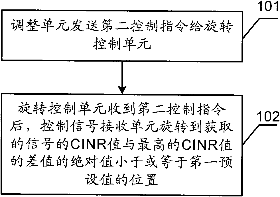
[0030] When the directional antenna needs to be adjusted, the adjustment unit 4 sends a first control command to the rotation control unit 3 . After the rotation control unit 3 receives the first control instruction, it controls ...


PUM


Abstract

The invention provides a directional antenna and the automatic adjustment method thereof. The directional antenna comprises an adjustment unit, a rotation control unit and a signal receiving unit, wherein the signal receiving unit is connected with the rotation control unit and is used for receiving signals and acquiring CINR (carrier to interference plus noise ratio) values of the signals; the adjustment unit is connected with the rotation control unit and is used for transmitting a second control instruction to the rotation control unit; and the rotation control unit is connected with the adjustment unit and the signal receiving unit, and is used for controlling the signal receiving unit to rotate to a position where the absolute value of the difference between the acquired CINR value of the signal and the highest CINR value is smaller than or equal to a first preset value after receiving the second control instruction transmitted by the adjustment unit. In the embodiment of the invention, the automatic adjustment of the directional antenna is achieved, which overcomes the inconvenience in manual adjustment.

Description

technical field [0001] Embodiments of the present invention relate to the field of communication technologies, and in particular to a directional antenna and an automatic adjustment method thereof. Background technique [0002] Antennas applied to terminals are generally divided into two types, ie, omnidirectional antennas and directional antennas. [0003] The omnidirectional antenna shows uniform radiation in 360 degrees on the horizontal pattern, without directionality. In the vertical pattern, it is shown as a beam with a certain width. Generally, the smaller the beam width, the greater the gain. Omni-directional antennas are used in communication systems for short distances, large coverage areas, and low prices, but low gain. [0004] The directional antenna has a certain angle of radiation range and directivity in the horizontal pattern, and a beam with a certain width in the vertical pattern. Like the omnidirectional antenna, the smaller the beam width, the greater ...

Claims


Application Information

Patent Timeline
Patent Type & Authority Applications(China)
IPC IPC(8): H01Q3/04
CPCH01Q3/04H01Q1/1257
Inventor 江胜峰
Owner HUAWEI TECH CO LTD
Why Eureka
Try Eureka