Device and method for winding sheared waste from steel band edges

An edge and waste technology, applied in the field of edge shearing waste devices, can solve problems such as hard work and achieve the effect of increasing the distance

Inactive Publication Date: 2011-05-18
CLECIM SAS
View PDF4 Cites 7 Cited by
  • Summary
  • Abstract
  • Description
  • Claims
  • Application Information

AI Technical Summary

Problems solved by technology

The job is extremely hard and

Method used


Image

  • Device and method for winding sheared waste from steel band edges
  • Device and method for winding sheared waste from steel band edges
  • Device and method for winding sheared waste from steel band edges

Examples


Embodiment Construction

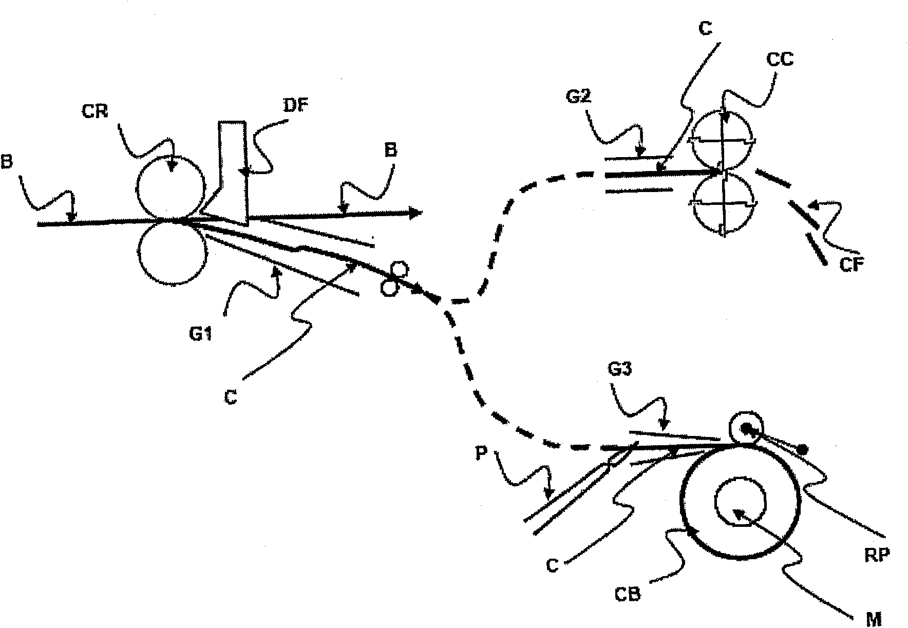
[0042] figure 1 Side view showing the principle of operation of the edge shear CR and removal of the scrap C, i.e. a view in the direction of travel of the strip B whose edges are sheared to form scrap to be removed to the strapping machine .

[0043] The strip B thus passes through the edge shears CR and the waste C output from the two circular blades (on the right and left inner sides of the strip) is deflected by the deflector DF in the direction of the shredder or strapping device. The trough G1 is deflected. The edge cutter consists of two symmetrical heads, each cutting one of the two edges of the strip.

[0044] In the case of shredding, the scrap C arrives through an additional chute G2 between the rotating drums of the scrap cutter CC, whose knives ensure that the strip is cut across its width in a sequential and periodic manner. Broken off on the CF. Thus, the size of the resulting tape piece allows for easier removal.

[0045] In the case of strapping, the scrap ...


PUM


Abstract

The invention relates to a device and method for winding sheared waste obtained from the edges of continuously moving steel bands, including: an edge shear (CR) which diverts the edges into a chute (G1) that conveys same to an accumulation chamber (2) in which the edge waste is stored in the form of a ball (1); a bundling drum (7) including a winding axis located between two side faces of said drum; and a handling means (4) designed to direct the end of the ball from the accumulation chamber to the winding axis in order to initiate the winding of the ball. According to the invention, the device also includes a winding mandrel (6) which can be inserted along the winding axis of the drum through a central opening in one of the side faces of the drum. In mandrel insertion mode, a counter pressure element (722, 723) engages coaxially with the mandrel and the end of the ball is clamped between said counter pressure element and mandrel.

Description

technical field [0001] The invention relates to a device and a method for edge-sheared scrap of coiled steel strip as stated in the preambles of claims 1 and 6 . Background technique [0002] The present invention relates to the processing of a continuously moving steel strip and in particular to the continuous shearing of the edges or sides of said strip. [0003] In particular, the sides of the rolled strip may have different types of defects after hot rolling, especially cracks or "cracks", which must be passed, for example, by cold rolling, before continuing the processing operation of the strip to eliminate to eliminate breaks on the strip during these operations. On the other hand, rolled strip must be machined to the required width and within required tolerances before being supplied to the customer in coil form. For this purpose, the cutting of the side edge of the moving strip is performed using scissors with rounded blades which cut both edges of the edge simulta...

Claims


Application Information

Patent Timeline
IPC IPC(8): B21C47/04B21C47/32B21C49/00
CPCB21C47/267B21C47/04B21C47/32B21C49/00
Inventor X·布瓦西耶
Owner CLECIM SAS
Why Eureka
Try Eureka