Apparatus and method for controlling robot arm, robot, program for controlling robot arm, and integrated electronic circuit

A robot arm and control device technology, applied in the direction of program control manipulator, manipulator, program control, etc., can solve problems such as inability to perform accurate correction, inability to perform motion correction smoothly, and inability to perform motion correction.

Inactive Publication Date: 2011-05-18
PANASONIC CORP
View PDF1 Cites 10 Cited by
  • Summary
  • Abstract
  • Description
  • Claims
  • Application Information

AI Technical Summary

Problems solved by technology

[0010] However, this method has the following problem in comparison with the conventional teaching at the time of stop in order to perform motion correction by human operation during the robot motion: the motion parameters input by humans fluctuate and cannot be performed smoothly. Perform movement correction
For example, when the speed of the movement is fast, in terms of the movement correction performed by the person, especially at the start and end of the operation, the human finger is also corrected including the shaking, and the movement cannot be performed smoothly. to correct
Furthermore, since it can be corrected by a person during the movement, even a section where a large amount of force is applied instantaneously by mistake, such as when a person accidentally collides, will be corrected, and accurate correction cannot be performed.
In addition, when it is desired to correct only the force applied to the work object, errors such as position and speed are also corrected at the same time, and motion correction cannot be performed accurately.
In addition, the movement of the human is also directed to the direction of acceleration or deceleration of the movement of the robot arm, which cannot be corrected accurately by humans.
Furthermore, when correction is performed as a repetitive motion, the repetitive motion fluctuates depending on the application of human force, and accurate correction cannot be performed.
In addition, if humans do not understand the characteristics of the range of motion of the robot arm in detail, it is impossible to correct the desired motion in the vicinity of the range of motion for manipulation.
In addition, in the case of elderly people, handicapped people, children, etc., if the force to be applied to the work object is insufficient, accurate correction cannot be made.
Similarly, when it is desired to move a robot arm at a high speed, it cannot be corrected accurately when a human cannot operate at that speed.

Method used


Image

  • Apparatus and method for controlling robot arm, robot, program for controlling robot arm, and integrated electronic circuit
  • Apparatus and method for controlling robot arm, robot, program for controlling robot arm, and integrated electronic circuit
  • Apparatus and method for controlling robot arm, robot, program for controlling robot arm, and integrated electronic circuit

Examples


no. 1 approach

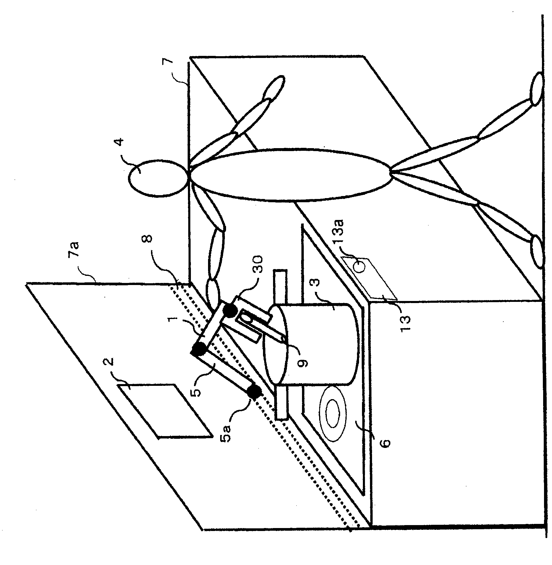
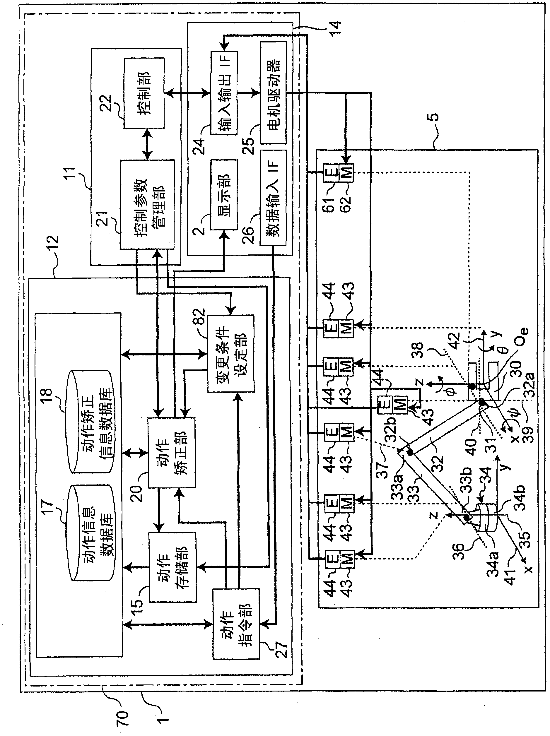
[0215] First, the structure of the robot system 1 provided with the control device of the robot arm in the first embodiment of the present invention will be described. figure 1 and figure 2 It is a schematic diagram showing the robot system 1 including the robot arm 5 and its control device 70 in the first embodiment of the present invention.

[0216] Such as figure 1 As shown, the robot arm 5 of the robot system 1 is, for example, installed on a wall 7a of a workbench 7 such as a kitchen or a desk at home, and the base end 5a of the robot arm 5 is supported in a movable manner relative to a guide rail 8 fixed on the wall 7a. , through the force exerted by the person 4, the robot arm 5 can be moved along the lateral direction (for example, the horizontal direction) on the guide rail 8 .

[0217] The robot system 1 cooperates with the robot arm 5 and the human 4 to perform tasks in the home, such as stirring the ingredients in the pot 3 with the robot arm 5 or wiping off the...

no. 2 approach

[0392] The basic configuration of the control device for the robot arm in the second embodiment of the present invention is the same as that in the first embodiment, so the description of the common parts will be omitted, and only the different parts will be described in detail below.

[0393] As in the case of the first embodiment, if Figure 8A As shown, the case where the robot system 1 is used to perform the stirring operation of the pot 3 is taken as an example for description.

[0394] —Action Correction Information Database—

[0395] Figure 16 A movement correction information database 18 is shown. It is configured to have a motion correction information ID number as an ID for identifying the motion correction information (refer to Figure 16 "Motion correction information ID" column); it is the information involved in the correction interval (refer to Figure 16 "Correction interval" column) and is the information related to the threshold value of the force when t...

no. 3 approach

[0401] The basic configuration of the control device for the robot arm in the third embodiment of the present invention is the same as that in the first embodiment, so the description of the common parts will be omitted, and only the different parts will be described in detail below.

[0402] As in the case of the first embodiment, if Figure 8A As shown, the case where the robot system 1 is used to perform the stirring operation of the pot 3 is taken as an example for description.

[0403] —Action Correction Information Database—

[0404] Figure 18 A movement correction information database 18 is shown. It is configured to have a motion correction information ID number as an ID for identifying the motion correction information (refer to Figure 18 "Motion correction information ID" column); it is the information involved in the correction interval (refer to Figure 18 "Correction interval" column) and is the information related to the threshold value of the force when th...


PUM


Abstract

An apparatus for controlling a robot arm performs operations using a robot arm (5) by controlling the movement of the robot arm (5). The apparatus corrects movement information by means of a movement correcting section (20), corresponding to movement correcting information relating to a method for correcting the movement information relating to the movement of the robot arm with respect to the operations performed to the robot arm by a human, and a human force detected by a force detecting section (53), while the robot arm (5) is moving.

Description

technical field [0001] The present invention relates to a control device and a control method of a robot arm for generating and teaching the motion of a robot, a robot having a control device for the robot arm, a program of the robot arm, and an integrated electronic circuit. Background technique [0002] In recent years, home robots such as care robots and housework support robots have been actively developed. Unlike industrial robots, home robots must be operated by amateurs at home, so it is necessary to be able to teach motion easily. Furthermore, since the operating environment during robot work is also varied depending on the household, it is necessary to flexibly respond to the household environment. [0003] As an example of the teaching method of the robot device, a force sensor is attached to the wrist of the robot, etc., and the teacher directly holds the handle attached to the front end of the force sensor, guides the robot to the teaching point, and performs te...

Claims


Application Information

Patent Timeline
Patent Type & Authority Applications(China)
IPC IPC(8): B25J9/10B25J9/22
CPCG05B2219/39325B25J9/0003G05B19/423B25J13/085G05B2219/37357G05B2219/40411
Inventor 津坂优子
Owner PANASONIC CORP
Why Eureka
Try Eureka