
Method and device for inserting springs into a groove

A technology of tenon and tenon groove, applied in the field of devices implementing this method, can solve problems such as prone to failure

Inactive Publication Date: 2012-12-26
吉多舒尔特
View PDF4 Cites 0 Cited by
  • Summary
  • Abstract
  • Description
  • Claims
  • Application Information

AI Technical Summary

Problems solved by technology

Although it is possible to separate the tenons individually (into individual tenons) and thereby orient them, for example by vibrating means, so that the storage bin can be filled, it is prone to failure for such small volume components

Method used


Image

  • Method and device for inserting springs into a groove

Examples


Embodiment Construction

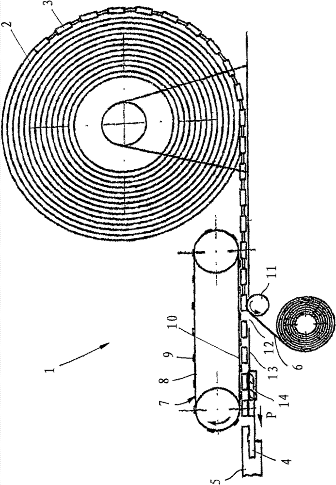
[0029] In a very schematic illustration, a device 1 is shown, by means of which a tenon 3 wound on a material roll 2 can be inserted into the tenon and groove 4 of the unit panels 5 laid in combination.

[0030] The device 1 is used for processing tenons 3 which are detachably connected to a supply belt 6 , in particular by gluing. In the device 1 the tongues 3 are released from the supply belt 6 . After the tenon 3 has been released, the supply tape 6 is wound and the supply tape can be reloaded with the tenon 3.

[0031] The tenons 3 are fastened at constant distances to the supply belt 6 and are conveyed inside the device from right to left in the plane of the drawing. The further conveyance of the tenons 3 takes place via a belt conveyor 7 which has a flat conveyor belt 8 provided with a plurality of drivers 9 . The drivers 9 are arranged at the same distance as the tenons 3 on the supply belt 6 , so that a driver 9 always engages between two tenons 3 . The lower branch 1...


PUM


Abstract

The method involves providing springs (3) on a transition belt (6) by removably sticking springs on sections of the transition belt, where the transition belt is provided with the springs as a winding coil (2). The springs are detachably connected with the transition belt, where the transition belt exhibits a surface contour adapted to the geometry of the springs. The springs are released from the transition belt. The springs are shifted into a groove (4) in element plates (5) for locking the element plates with one another. An independent claim is also included for a spring inserting device comprising a drive unit.

Description

technical field [0001] The invention relates to a method for inserting a tenon into a tongue groove on a longitudinal or top side of a unit panel and a device for carrying out this method. Background technique [0002] WO 2008 / 017301 A2 discloses a prior art floor covering consisting of a plurality of unit panels laid in combination with each other on their top side and in their longitudinal sides with Locking strips which, in the installed position, engage adjacent cell panels in the cladding into one another. Here, a tongue groove is provided in the top side, wherein the tongue grooves of two adjoining top sides correspond and form a locking channel for receiving the top tongue. The top tongue is pre-mounted in the tongue groove and protrudes beyond one end of the tongue groove facing the longitudinal side of the cell plate. At the same time the top tenon completely encloses (gekammert) inside the tenon groove in the pre-assembled state and can be moved at least partiall...

Claims


Application Information

Patent Timeline
Patent Type & Authority Patents(China)
IPC IPC(8): B27M3/04E04F15/02
CPCB27M3/04E04F2201/0541E04F2201/0138E04F2201/0523E04F15/02038B27M3/0066E04F2201/0153Y10T29/53613Y10T29/49872Y10T29/49901Y10T29/49863
Inventor 吉多·舒尔特
Owner 吉多舒尔特
Learn More