Hose clamps

A technology of hose clamps and hoses, applied in the field of hose clamps, can solve problems such as high cost and achieve high-strength effects

Active Publication Date: 2011-05-18
OETIKER SCHWEIZ AG
View PDF8 Cites 4 Cited by
  • Summary
  • Abstract
  • Description
  • Claims
  • Application Information

AI Technical Summary

Problems solved by technology

This problem can be solved by using high qualit

Method used


Image

  • Hose clamps
  • Hose clamps
  • Hose clamps

Examples


Embodiment Construction

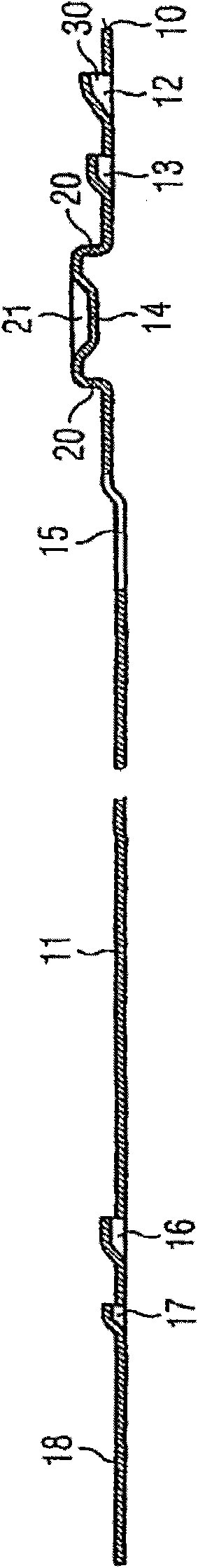
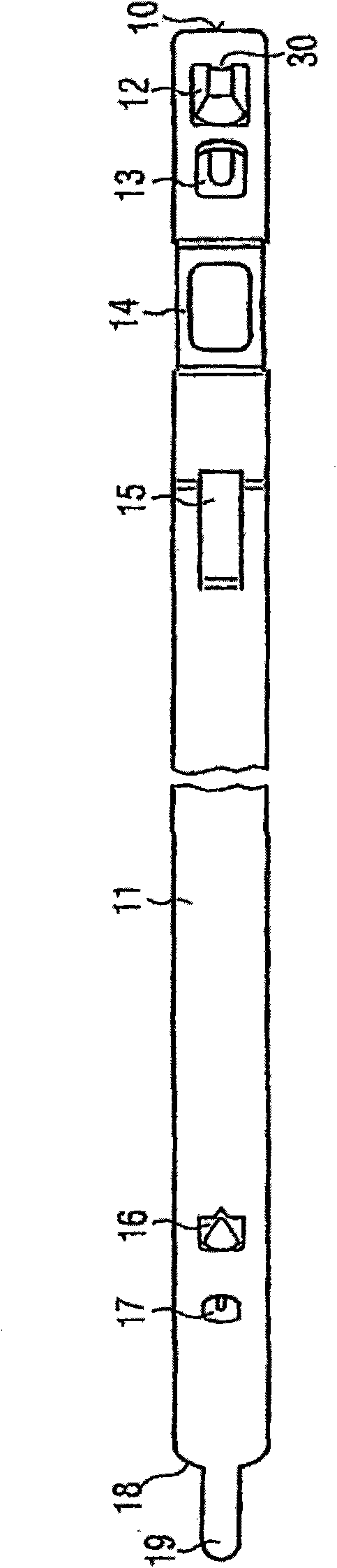
[0014] from figure 1 with figure 2 Proceeding from the band end 10 shown on the right, which is located on the outside in the closed state of the hose clamp, the hose clamp illustrated in the drawing has the following features formed from a steel band 11 by cold forming: Guide receiver 12, holding receiver 13, tensioning device 14 in the form of a so-called "Oetiker-Ohr", tongue guide 15, guide hook 16, holding hook 17, and in soft A tongue 19 on the other inner strap end 18 in the closed state of the pipe clip.

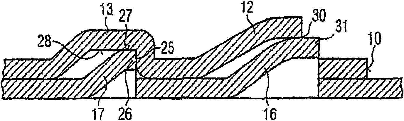
[0015] exist image 3 In the closed state of the hose clamp shown in , the guide hook 16 engages in the guide receptacle 12 , the retaining hook 17 engages in the retaining receptacle 13 and the tongue 19 engages in the tongue guide 15 .

[0016] In order to tighten the hose clamp by reducing the diameter of the hose clamp, two legs 20 of the tensioning lug (Spannohr) 14 originating from the belt and extending substantially perpendicularly to the belt are placed ...


PUM


Abstract

The invention relates to a hose clamp, whereby the connection of the two ends of the band 10, 18 is made by a guide hook 16 disposed on the inner band region and engaging in a guide receptacle 12 on the outer end of the band, and a retaining hook 17 also provided on the inner band region and engaging in a retaining receptacle 13 on the outer band region. The mounting receptacle 13 is formed as an embossment formed from the band material and attached to the band material on all sides, the inner surface thereof transitioning perpendicular to the band surface into a support region 25 adjacent to the outer end of the band 10. The retaining hook 17 has a dog facing away from the inner end of the band 18, a cutting edge of said dog engaging in the support region 25 of the retaining receptacle 13 when the hose clamp is tightened. Because it is configured as one piece with the band material, the retaining receptacle 13 has much greater strength than conventional penetrations or cutouts in the band.

Description

Background technique [0001] A hose clamp with the features given in the first part of claim 1 is known from US 4,299,012. Due to the fact that the inner surface of this hose clamp has no gaps or steps in the tensioned state and thus supports the hose over the entire circumference of the hose, it has also proved useful for fastening thin, stiff hoses to the pipe wrench. [0002] For connecting the outer strap end to the inner strap region, known hose clamps have guide hooks arranged on the inner strap region and at least one supporting or retaining hook. In the closed state, the guide hook and the retaining hook each engage in a recess formed in the region of the outer band. [0003] As hoses become increasingly thinner and less elastic with a corresponding increase in the required tension, the hook connection has a weak point. This manifests itself in the elongation and eventual tearing of the adjacent tensioning means, for example the so-called "Oetiker Ohr", under too high...

Claims


Application Information

Patent Timeline
IPC IPC(8): F16L33/025F16L33/035
CPCF16L33/035F16L33/025Y10T24/1412Y10T24/1478Y10T24/1482F16L33/02F16B2/08
Inventor 乌尔里克·梅尔威利·汉斯利
Owner OETIKER SCHWEIZ AG
Why Eureka
Try Eureka