Method for turning counterbores at two ends

A processing method and counterbore technology, which is applied in the processing field with counterbore at both ends, and can solve the problem that the coaxiality of counterbore on both ends cannot be guaranteed.

Inactive Publication Date: 2011-05-25
SHANDONG HUALI ELECTRIC MOTOR GRP
View PDF5 Cites 1 Cited by
  • Summary
  • Abstract
  • Description
  • Claims
  • Application Information

AI Technical Summary

Problems solved by technology

[0003] In order to solve the problem that the coaxiality of the counterbore at both ends cannot be guaranteed, the present invention provides a turning process method with counterbore at both ends

Method used


Image

  • Method for turning counterbores at two ends
  • Method for turning counterbores at two ends
  • Method for turning counterbores at two ends

Examples


Embodiment Construction

[0015] The present invention will be further described below in conjunction with embodiment.

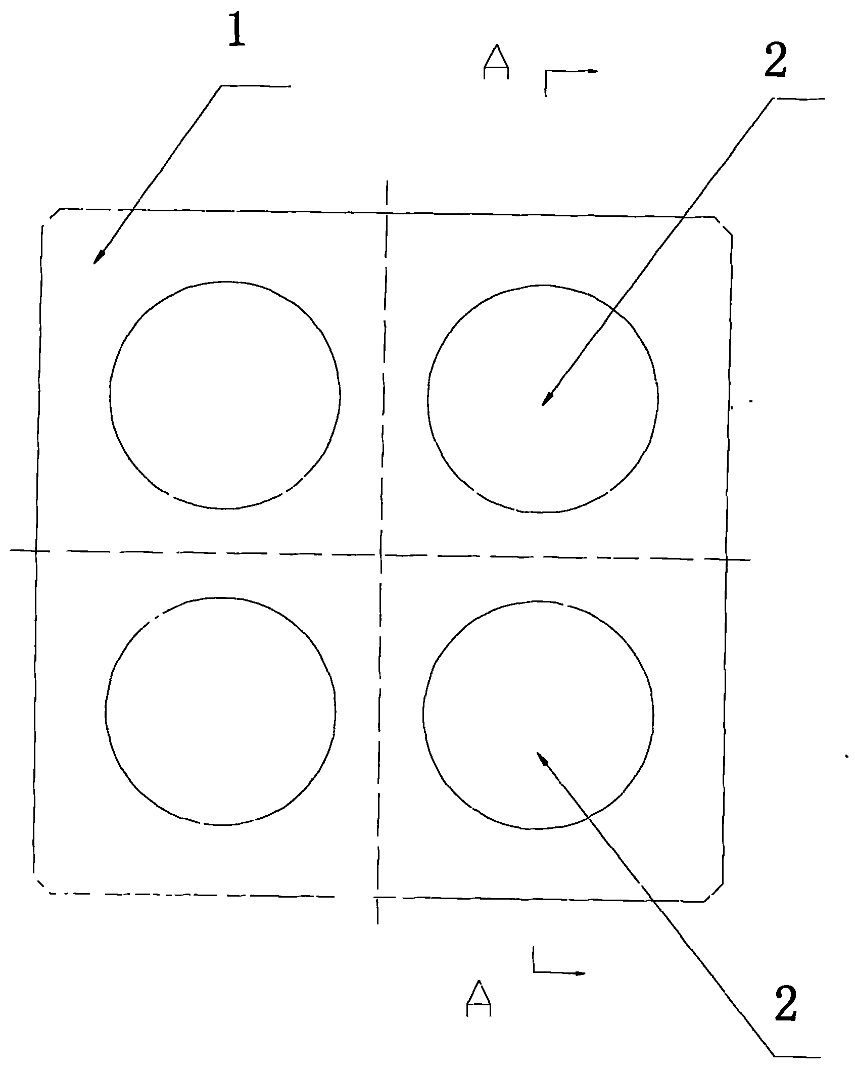
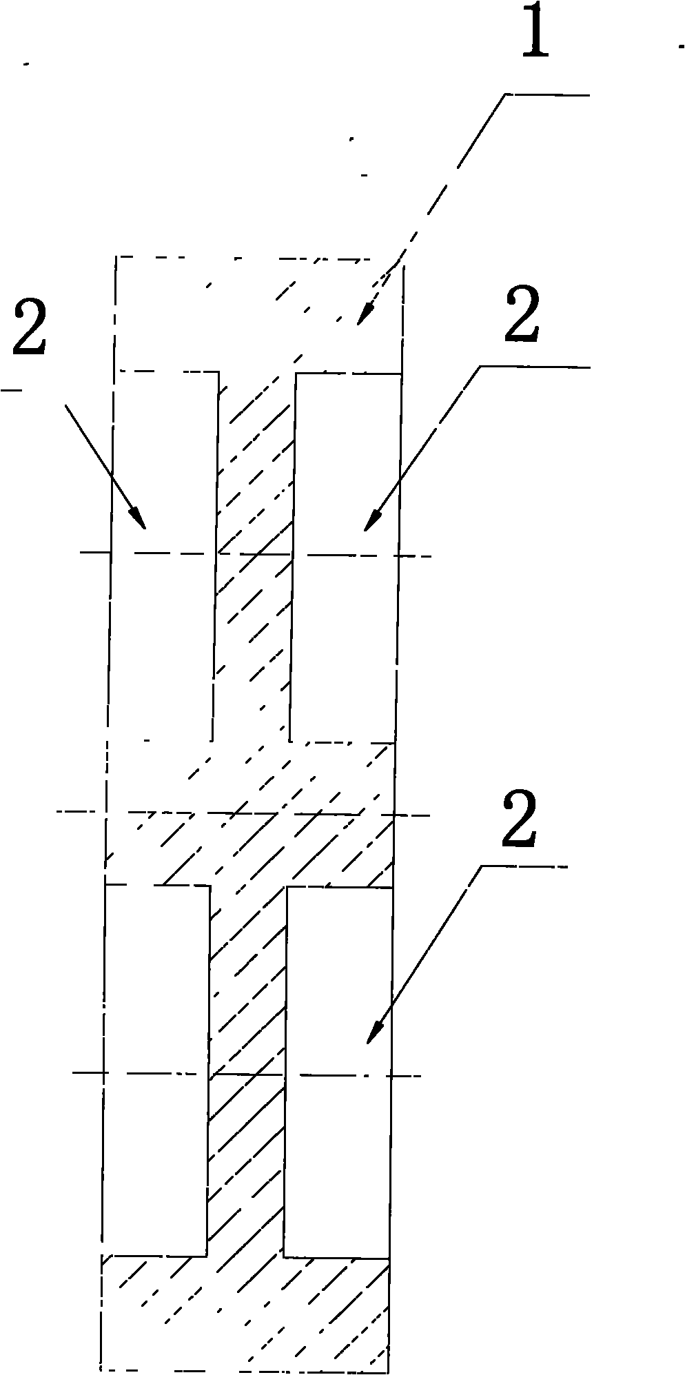
[0016] like figure 1 , 2 As shown, a part 1 to be processed has two end faces, and each end face is processed with four counterbores 2. It is required that the corresponding counterbores 2 on both sides of the end face should be on the same axis. The processing steps are as follows:

[0017] 1: According to the requirements of the drawings, blank, plan, mark, drill small holes, and drill the center hole for part 1. Use the top 5 of the lathe to withstand the center hole, and clamp it with the four-jaw chuck 6 at the same time, and the other end of the part is countersunk. 2;

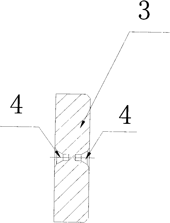
[0018] 2: Processing tooling such as image 3 As shown, the two ends of the tooling are milled out, and the center hole 4 is drilled at the same time. The outer circle of the tooling 3 is processed with the two center holes 4 at the top of the lathe. The diameter match;

[0019] 3. If Figure 4 As shown, ...


PUM


Abstract

The invention relates to a method for turning counterbores at two ends. In order to solve the problem that coaxiality of counterbores at two ends can not be ensured, the method for turning the counterbores at two ends provided by the invention has the following steps: 1) turning a counterbore in one end surface of a processed part; 2) processing a circular tooling part in accordance with the diameter of the counterbore, processing a center bore in the circle center of the tooling part, and forming interference fit by matching the diameter of the tooling part with the diameter of the counterbore; and 3) assembling the processed tooling part and the processed counterbore as a whole in a manner of little interference, and turning the counterbore in the other end of the part by using a lathe center to hold the center bore of the tooling part. In the method for turning the counterbores at two ends provided by the invention, the self-made tooling part is adopted, the processing position of each counterbore is located by the center bore, and the counterbores at two ends of the processed part can be ensured to be on the same axis, thereby meeting the drawing requirements.

Description

technical field [0001] The invention relates to a processing method with counterbore holes at both ends, especially a processing method requiring higher precision for the coaxiality of the counterbore holes at both ends. Background technique [0002] In actual production, the figure 1 The counterbore holes on both ends of the parts shown should be processed, and the requirements specified in the drawings must be ensured during processing. The traditional processing technology is blanking → planing → scribing and punching → drilling small holes → reaming → transfer to the other end surface for scribing and punching → drilling small holes → reaming. This method of scribing and drilling the counterbore leads to the fact that the coaxiality of the counterbore on both ends of the machined part cannot be guaranteed. The main reasons are: 1. The fitter draws the line. When drawing the line, there is a perpendicularity error between the scribing reference plane and the scribing su...

Claims


Application Information

Patent Timeline
Patent Type & Authority Applications(China)
IPC IPC(8): B23B1/00
Inventor 吕桂梅于海军宋建明刘会珍丁娟
Owner SHANDONG HUALI ELECTRIC MOTOR GRP
Why Eureka
Try Eureka