Detection method for swirl holes in nozzle swirl plate of aircraft engine

An aero-engine and detection method technology, which is applied in the field of measurement, can solve the problems of scrapped nozzles, inability to measure, and affect the atomization performance indicators of nozzles, and achieve the effect of ensuring atomization performance.

Inactive Publication Date: 2015-01-14
CHINA HANGFA GUIZHOU LIYANG AVIATION POWER CO LTD
View PDF5 Cites 2 Cited by
  • Summary
  • Abstract
  • Description
  • Claims
  • Application Information

AI Technical Summary

Problems solved by technology

At present, the above dimension a and dimension b cannot be measured, and can only be guaranteed through the processing process
Its disadvantages are: due to problems such as tool setting errors and unavoidable tool wear during processing, there may be a possibility of out-of-tolerance dimensions a and b. If the dimensions a and b are out of tolerance, the atomization performance index of the nozzle will be affected. Even cause the nozzle to be scrapped

Method used


Image

  • Detection method for swirl holes in nozzle swirl plate of aircraft engine
  • Detection method for swirl holes in nozzle swirl plate of aircraft engine
  • Detection method for swirl holes in nozzle swirl plate of aircraft engine

Examples


Embodiment 1

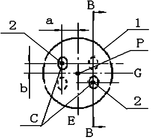
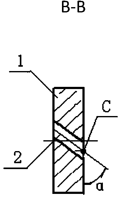
[0026] Drawings require dimension a=0.75±0.012mm, b=0.42±0.012mm, and the detection steps of dimension a and dimension b are as follows:

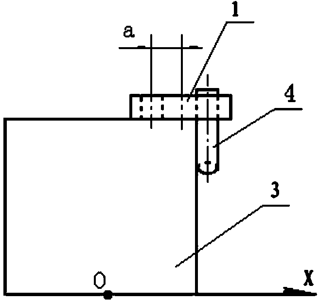
[0027] 1. Assemble the locating pin: Insert the upper end of the locating pin 4 into the vortex hole 2 from the lower port of the vortex hole 2 of the nozzle vortex sheet 1. The locating pin 4 is a cylindrical pin with an outer diameter of 0.518mm;

[0028] 2. Place the nozzle vortex sheet 1: place the nozzle vortex sheet 1 with the positioning pin 4 on the upper surface of the detection platform 3 to ensure that the lower surface of the nozzle vortex sheet 1 fits with the upper surface of the detection platform 3, and the position of the positioning pin 4 The outer circular surface is attached to the side of the detection platform 3, and the detection platform 3 is a cube; 502 glue is applied to the bonding seam between the lower surface of the nozzle vortex sheet 1 and the upper surface of the detection platform 3;

[0029] 3. Measure the...

Embodiment 2

[0035] Drawings require dimensions a=0.75±0.012mm, b=0.42±0.012mm, and the detection steps of a and b are as follows:

[0036] 1. Assemble the positioning pin: Insert the upper end of the positioning pin 4 into the vortex hole 2 from the lower port of the vortex hole 2 of the nozzle vortex sheet 1. The positioning pin 4 is a cylindrical pin with an outer diameter of 0.52mm;

[0037] 2. Place the nozzle vortex sheet 1: place the nozzle vortex sheet 1 with the positioning pin 4 on the upper surface of the detection platform 3 to ensure that the lower surface of the nozzle vortex sheet 1 fits with the upper surface of the detection platform 3, and the position of the positioning pin 4 The outer circular surface is attached to the side of the detection platform 3, and the detection platform 3 is a cube; 502 glue is applied to the bonding seam between the lower surface of the nozzle vortex sheet 1 and the upper surface of the detection platform 3;

[0038] 3. Measure the center coo...

Embodiment 3

[0044] Drawings require dimensions a=0.75±0.012mm, b=0.42±0.012mm, and the detection steps of a and b are as follows:

[0045] 1. Assemble the locating pin: Insert the upper end of the locating pin 4 into the vortex hole 2 from the lower port of the vortex hole 2 of the nozzle vortex sheet 1. The locating pin 4 is a cylindrical pin with an outer diameter of 0.515mm;

[0046] 2. Place the nozzle vortex sheet 1: place the nozzle vortex sheet 1 with the positioning pin 4 on the upper surface of the detection platform 3 to ensure that the lower surface of the nozzle vortex sheet 1 fits with the upper surface of the detection platform 3, and the position of the positioning pin 4 The outer circular surface is attached to the side of the detection platform 3, and the detection platform 3 is a cube; 502 glue is applied to the bonding seam between the lower surface of the nozzle vortex sheet 1 and the upper surface of the detection platform 3;

[0047] 3. Measure the center coordinate ...


PUM


Abstract

The invention belongs to measuring technologies and relates to a detection method for swirl holes in a nozzle swirl plate of an aircraft engine. The method comprises the following detection steps of assembling positioning pins, placing the nozzle swirl plate (1), measuring central coordinate values of the nozzle swirl plate (1), detecting the size a and detecting the size b. According to the detection method for the swirl holes in the nozzle swirl plate of the aircraft engine, the size a and the size b can be measured accurately, it is guaranteed that the size a and the size b meet requirements of drawings, and the atomization performance of a nozzle is guaranteed.

Description

technical field [0001] The invention belongs to the measurement technology, and relates to a method for detecting swirl holes on a swirl sheet of an aero-engine nozzle. Background technique [0002] For the structure of the nozzle swirl plate of a certain type of aero-engine, see figure 1 , 2 . The nozzle swirl sheet is one of the important atomizing elements in the nozzle, it is a thickness of Outer circle diameter D=3 -0.01 mm disc, there are two through swirl holes 2 on the upper surface of the nozzle swirl sheet 1, the two swirl holes 2 are symmetrical to the axis of the nozzle swirl sheet 1, the center point C of the upper port of the swirl hole 2 is to the nozzle swirl sheet 1 The distance b=0.42±0.012mm from the horizontal center line G, the distance a=0.75±0.012mm from the center point C of the upper port of the swirl hole 2 to the vertical center line E of the nozzle swirl sheet 1, the axis of the swirl hole 2 and the nozzle swirl sheet 1 The vertical split pl...

Claims


Application Information

Patent Timeline
Patent Type & Authority Applications(China)
IPC IPC(8): G01B11/03
Inventor 熊成红姜智李克然郑忠俊刘祖雄韩伦珍
Owner CHINA HANGFA GUIZHOU LIYANG AVIATION POWER CO LTD
Why Eureka
Try Eureka