Flame denitration combustor device and flame denitration system

A denitrification burner and flame technology, which is applied in the field of nuclear engineering, can solve problems such as difficult to ensure stable reaction and less products, achieve stable combustion, improve stability, and ensure the effect of atomization

Pending Publication Date: 2021-09-03
CHINA NUCLEAR POWER ENG CO LTD
View PDF8 Cites 3 Cited by
  • Summary
  • Abstract
  • Description
  • Claims
  • Application Information

AI Technical Summary

Problems solved by technology

[0004] The burner is the core component of the flame denitrification method, but there are few such products at present, and the existing products are difficult to guarantee the stable progress of the reaction

Method used


Image

  • Flame denitration combustor device and flame denitration system
  • Flame denitration combustor device and flame denitration system
  • Flame denitration combustor device and flame denitration system

Examples


Embodiment 1

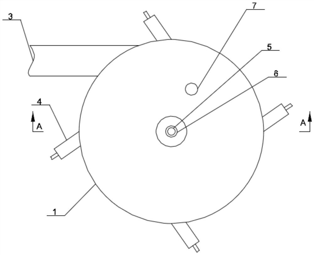
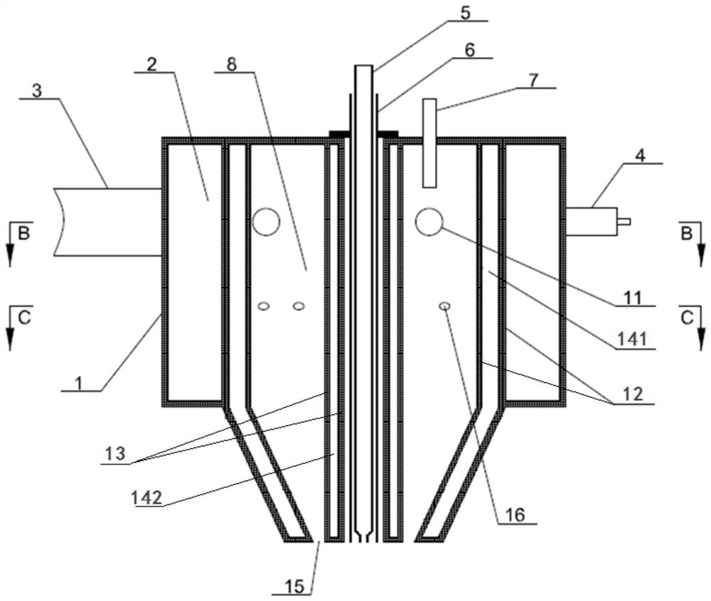
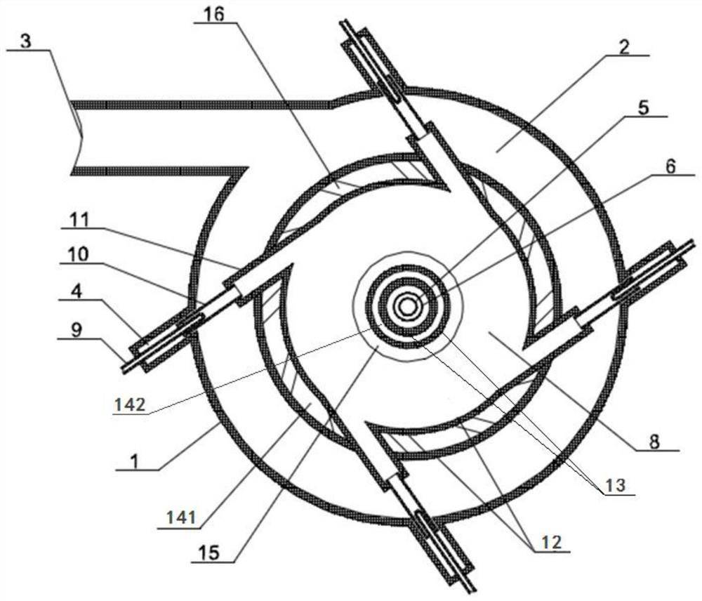
[0042] Such as Figure 1-Figure 5 As shown, this embodiment discloses a flame denitrification burner device, which includes a flame chamber 8, a combustion head 4, and a material nozzle 5, wherein: the combustion head 4 communicates with the flame chamber 8, and is used to pass into the flame chamber 8. A mixture of fuel and air; the mixture ignites the fuel in the flame chamber and generates high-temperature gas; the flame chamber 8 is provided with a combustion gas outlet 15, and the fuel gas outlet 15 is located at the end of the combustion head 4, and the center of the flame chamber 8 has Through the inner hole, the material nozzle 5 is arranged in the through inner hole of the flame chamber 8 and runs through the flame chamber 8, the material nozzle 5 is used to circulate uranyl nitrate, the outlet position of the material nozzle 5 and the position of the fuel gas outlet 15 are the flame chamber 8 The same end of the same end, so that the uranyl nitrate ejected from the m...

Embodiment 2

[0058] This embodiment discloses a flame denitration fuel device, which differs from the flame denitration burner device described in Embodiment 1 in that it also includes a pressurizing mechanism,

[0059] The pressurizing mechanism is used to pressurize the air before the air is passed into the air chamber 2, so that the air has a relatively high pressure. After the pressurized air enters the flame chamber 8, it will promote the gas in the flame chamber 8 to form a high-speed The rotating high-pressure and high-temperature gas, after contacting the uranyl nitrate ejected from the material nozzle 5, the high-pressure and high-temperature gas will not only heat the uranyl nitrate, but also atomize the uranyl nitrate.

[0060] Moreover, since the device is equipped with a pressurizing mechanism, the material nozzle 5 can be an ordinary material nozzle 5, that is, the material nozzle 5 does not have the function of atomizing uranyl nitrate, but only plays the role of transporting...

Embodiment 3

[0062] This embodiment discloses a flame denitration system, which includes the flame denitration burner device described in Embodiment 1 or 2.


PUM


Abstract

The invention discloses a flame denitration combustor device. The device comprises a flame cavity, a combustion head and a material nozzle, wherein the combustion head communicates with the flame cavity and used for introducing mixed gas of fuel gas and air into the flame cavity, the mixed gas is ignited and combusted in the flame cavity and generates high-temperature gas, the flame cavity is provided with a combustion gas outlet, the combustion gas outlet is formed in the end, away from the combustion head, of the flame cavity, a penetrating inner hole is formed in the center of the flame cavity, the material nozzle is arranged in the penetrating inner hole of the flame cavity, penetrates through the flame cavity and is used for circulating uranyl nitrate, and a position of an outlet of the material nozzle and a position of the combustion gas outlet are at the same end of the flame cavity, so that the uranyl nitrate sprayed by the material nozzle can make contact with the high-temperature gas discharged from the combustion gas outlet to perform a denitration reaction. The invention further discloses a flame denitration system comprising the flame denitration combustor device. According to the device, stable operation of the uranyl nitrate denitration reaction can be ensured.

Description

technical field [0001] The invention belongs to the technical field of nuclear engineering, and in particular relates to a flame denitration burner device and a flame denitration system including the flame denitration burner device. Background technique [0002] In the nuclear fuel cycle system, uranyl nitrate solution is obtained after extraction and purification. In order to process the uranyl nitrate solution into metal uranium or other uranium compounds, the uranyl nitrate can be converted into uranium oxides first. Since the dry denitrification process has obvious advantages in reagent consumption, waste liquid generation, operating costs, and tail gas treatment, dry denitrification processes are used at home and abroad to convert uranyl nitrate into UO 3 product. [0003] At present, the most typical dry denitrification process in China is the fluidized bed denitrification method, but the UO produced by the fluidized bed denitrification method 3 The specific surface ...

Claims


Application Information

Patent Timeline
Patent Type & Authority Applications(China)
IPC IPC(8): F23D14/02F23D14/48F23D14/64F23D14/70F23D14/78B01D53/56B01D53/78
CPCF23D14/02F23D14/64F23D14/70F23D14/48F23D14/78B01D53/78B01D53/56F23D2203/007
Inventor 李硕纪雷鸣李思凡陈勇侯学锋侯留东王博李银华
Owner CHINA NUCLEAR POWER ENG CO LTD
Why Eureka
Try Eureka