Fluid electromagnetic valve type metering ejector

A technology of solenoid valves and injectors, applied in fuel injection devices, machines/engines, exhaust gas treatment, etc., can solve problems such as insufficient atomization effect

Pending Publication Date: 2020-10-20
LIUZHOU YUANCHUANG EFI TECH
View PDF1 Cites 2 Cited by
  • Summary
  • Abstract
  • Description
  • Claims
  • Application Information

AI Technical Summary

Problems solved by technology

However, this patent only uses the change of pressure difference to atomize the urea solution, and its atomization effect is not good enough.

Method used


Image

  • Fluid electromagnetic valve type metering ejector
  • Fluid electromagnetic valve type metering ejector
  • Fluid electromagnetic valve type metering ejector

Examples


Embodiment 1

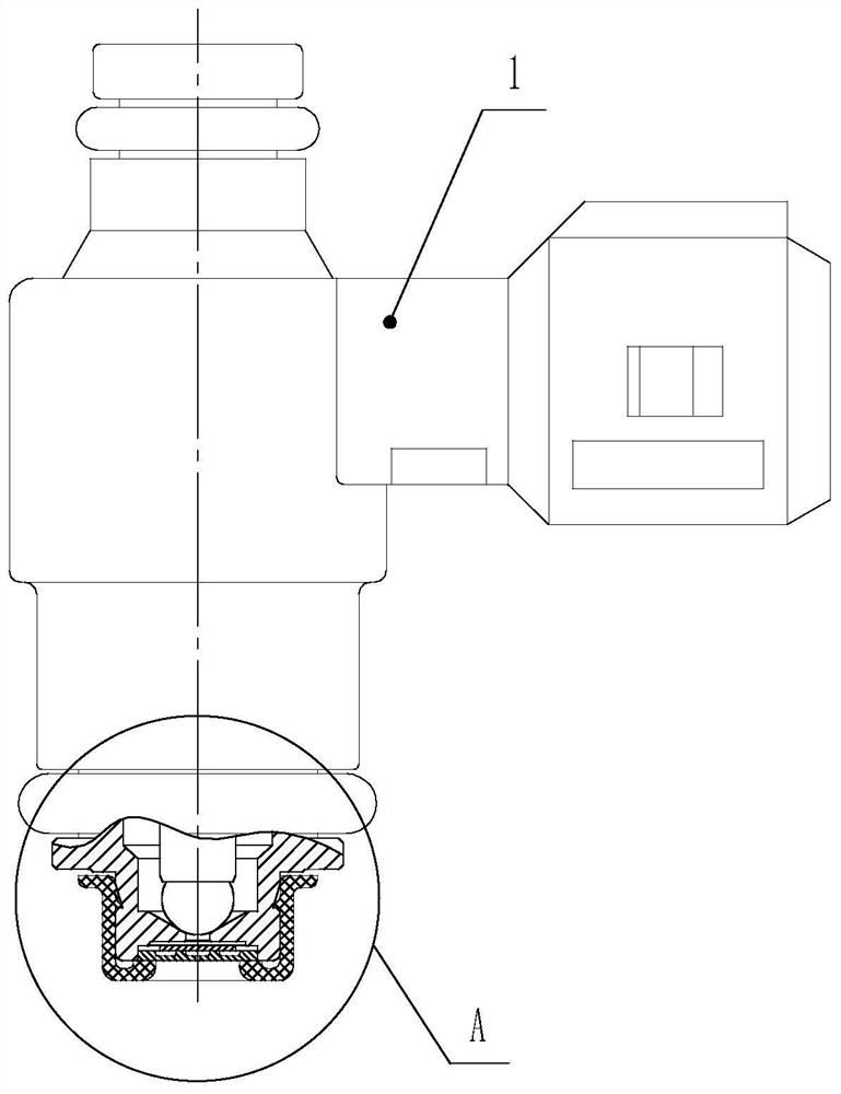
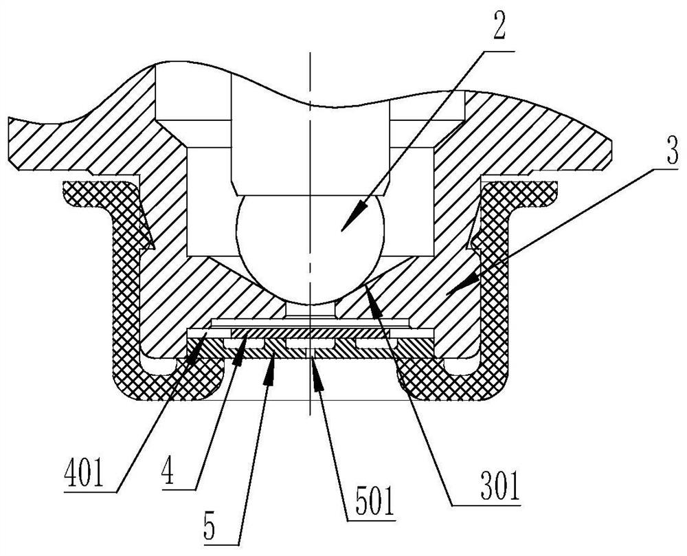
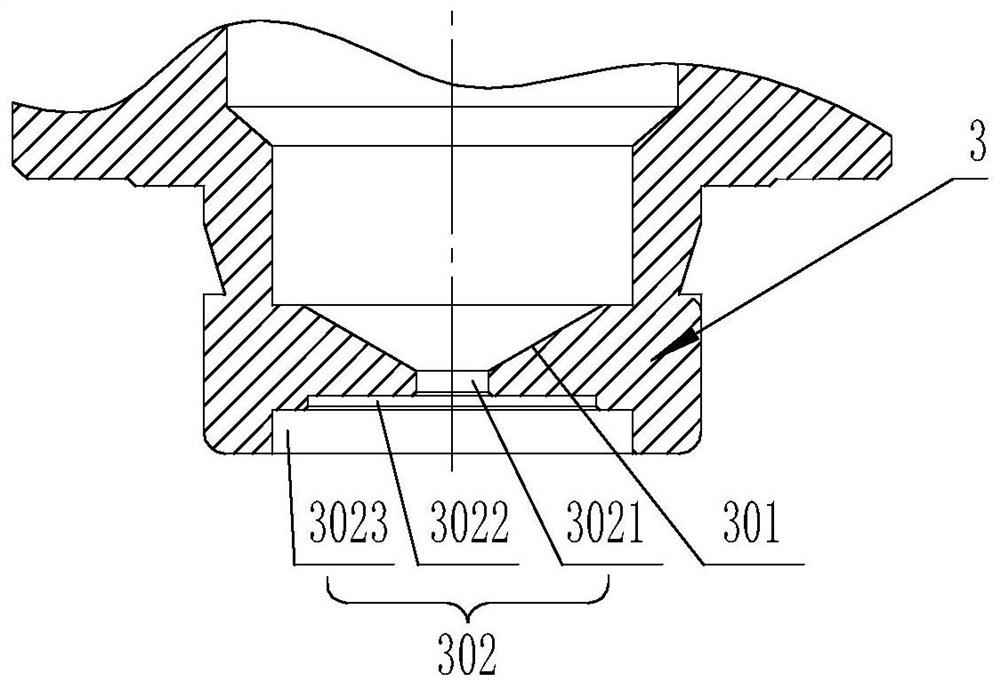
[0046] figure 1 Disclosed in is a fluid solenoid valve metering injector, which comprises a solenoid valve spray body 1 with a fluid input port, a nozzle with a spray hole, and the nozzle includes a valve seat 3 with a valve hole 301 1. The sealing steel ball 2 installed at the valve hole 301, the middle hole of the valve seat 3 positioned at the front end of the valve hole 301 is a stepped hole 302, and the stepped hole includes a first stepped hole 3021, a second stepped hole whose diameter gradually increases from inside to outside. Step hole 3022, third step hole 3023; wherein the first step hole 3021 is connected to the valve hole 301, and the third step hole 3023 is installed with a splitter 4 and a turbulent nozzle orifice plate 5 sequentially from the inside to the outside, and the flow sheet 4 is along the diameter The center of the turbulent nozzle orifice plate 5 is coaxially provided with a circular turbulent flow chamber Q1 and the spray hole 501, and the circumfe...

Embodiment 2

[0049] Figure 5 Disclosed in is another fluid solenoid valve type metering injector, the structure of which is basically the same as that of Embodiment 1, the difference is that: the turbulent flow orifice plate 5 is a split structure, the turbulent The flow orifice plate 5 is composed of a turbulent flow plate 51 and an orifice plate 52, and the turbulent flow plate 51 and the orifice plate 52 are installed on the outside of the shunt plate 4 sequentially from the inside to the outside; the turbulent flow chamber Q1 and the centrifugal turbulent flow groove Q2 is set on the turbulence sheet 51 , and the spray hole 501 is set on the spray hole plate 52 .

[0050] The specific dimensions of the split flow tank 401 , the turbulent flow chamber Q1 , the centrifugal turbulent flow tank Q2 , and the spray hole 501 are all different.

[0051] The specific structure of the fluid electromagnetic valve type metering injector described in the second embodiment is as follows:

[0052]...


PUM


Abstract

The invention relates to an ejector, in particular to a fluid electromagnetic valve type metering ejector. The fluid electromagnetic valve type metering ejector comprises an electromagnetic valve typeejector body with a fluid input port and a nozzle with an atomizing hole; the nozzle comprises a valve seat with a valve hole and a sealing steel ball installed at the valve hole; a splitter and a turbulent flow orifice plate are sequentially installed in a valve seat middle hole located at the front end of the valve hole from inside to outside; the splitter is provided with a splitter groove inthe radial direction, a turbulent flow cavity and a spraying hole which are in communication with each other are coaxially formed in the center of the turbulent flow orifice plate, and at least two centrifugal turbulent flow grooves are evenly distributed in the circumference of the turbulent flow cavity; one end of each centrifugal turbulence groove is tangentially connected with the turbulence cavity to form a centrifugal structure; and the other end of each centrifugal turbulence groove is in communication with the splitter groove of the splitter sheet. According to the fluid electromagnetic valve type metering ejector, fluid atomization particles can be increased, the atomization effect of gasoline fluid can be guaranteed, exhaust emission of a gasoline engine meets the requirements oflaws and regulations, the problem of hole blockage caused by oil product quality difference can be solved, and the maintenance time of products is shortened.

Description

technical field [0001] The invention relates to an injector, in particular to a fluid electromagnetic valve type metering injector used in equipment with extremely high requirements on atomized particles and flow metering performance. Background technique [0002] Laws and regulations have increasingly stringent requirements on exhaust emissions from gasoline engines. At present, the size of the atomized particles of the solenoid valve injector used in gasoline engines is in the range of 85µm to 120µm, and the atomized particles are relatively coarse. Insufficient internal combustion leads to excessive KO and KO2 emissions in the tail gas, which does not meet the emission requirements of laws and regulations. The invention patent with the application publication number of CN102108891A discloses a urea solution solenoid valve injector. The injector uses the change of pressure difference to make the urea solution form a mist-like turbulent flow at the front end of the nozzle, ...

Claims


Application Information

Patent Timeline
Patent Type & Authority Applications(China)
IPC IPC(8): F01N3/20F01N3/28F02M61/16F02M61/18
CPCF01N3/2066F01N3/28F01N2610/02F01N2610/1453F02M61/16F02M61/18F02M61/1853
Inventor 莫韬郭前伟
Owner LIUZHOU YUANCHUANG EFI TECH
Why Eureka
Try Eureka