Hydrogenation reaction effluent air cooler suitable for high chlorine raw oil processing

A technology of hydrogenation reaction and raw oil, applied in the direction of heat exchanger type, heat exchanger shell, indirect heat exchanger, etc., can solve the problem of equipment manufacturing cost increase, multi-phase flow stratification, and the effect of washing ammonium salt cannot be achieved and other problems to achieve the effect of prolonging the service life, avoiding deposition and under-deposit corrosion

Inactive Publication Date: 2014-05-21
ZHEJIANG SCI-TECH UNIV
View PDF3 Cites 4 Cited by
  • Summary
  • Abstract
  • Description
  • Claims
  • Application Information

AI Technical Summary

Problems solved by technology

This kind of method can only increase the balanced distribution of multiphase flow in each tube bundle. After the multiphase flow enters the air-cooled tube bundle, the turbulent kinetic energy of the fluid decreases rapidly, and the stratification of multiphase flow will still occur. Not only can it not achieve better washing of ammonium salt effect, and it will bring problems such as increased system pressure loss and increased equipment manufacturing costs.

Method used


Image

  • Hydrogenation reaction effluent air cooler suitable for high chlorine raw oil processing
  • Hydrogenation reaction effluent air cooler suitable for high chlorine raw oil processing
  • Hydrogenation reaction effluent air cooler suitable for high chlorine raw oil processing

Examples


Embodiment Construction

[0018] The present invention will be further described below in conjunction with drawings and embodiments.

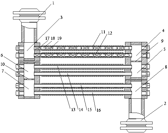
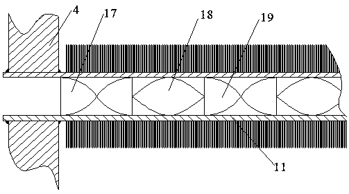
[0019] Such as figure 1 , figure 2 As shown, the present invention includes inlet flange 1, outlet flange 2, first tube box 3, second tube box 4, third tube box 5, fourth tube box 6, fifth tube box 7, sixth tube box 8. The first row of tube bundles 11, the second row of tube bundles 12, the third row of tube bundles 13, the fourth row of tube bundles 14, the fifth row of tube bundles 15, the sixth row of tube bundles 16, the first orifice plate 9, the second orifice plate 10, The first twisted sheet 17 and the second twisted sheet 18; the first tube box 3 and the second tube box 4 communicate through the first row of tube bundles 11 and the second row of tube bundles 12 arranged side by side, the second tube box 4 and the third tube bundle The boxes 5 are communicated through the first orifice plate 9, the third tube box 5 and the fourth tube box 6 are connected thro...


PUM


Abstract

The invention discloses a hydrogenation reaction effluent air cooler suitable for high chlorine raw oil processing. A first channel and a second channel are communicated through a first row of pipe bundles and a second row of pipe bundles, the first row of pipe bundles and the second row of pipe bundles are arranged in parallel, the second channel is communicated with a third channel through a first hole plate, the third channel is communicated with a fourth channel through a third row of pipe bundles and a fourth row of pipe bundles, the third row of pipe bundles and the fourth row of pipe bundles are arranged in parallel, the fourth channel is communicated with a fifth channel through a second hole plate, and the fifth channel is communicated with a sixth channel through a fifth row of pipe bundles and a sixth row of pipe bundles, wherein the fifth row of pipe bundles and the sixth row of pipe bundles are arranged in parallel. Twisted pieces are fixedly connected in a first row of pipe bundle holes and a second row of pipe bundle holes. The first channel is connected with an inlet flange, the sixth channel is connected with an outlet channel, and heat dissipation pieces are arranged outside the six pipe bundles. According to the hydrogenation reaction effluent air cooler, the turbulent mixing effect of oil-gas-water three-phase flow of reaction effluent is strengthened, layered flow is avoided, crystallized ammonium salt particles crystallized in the hydrogenation reaction effluent in the processing process of high chlorine raw oil can be fully washed, ammonium salt deposition and under-deposit corrosion are avoided, and the safety running period and the service life of the hydrogenation reaction effluent air cooler are prolonged.

Description

technical field [0001] The invention relates to an air cooler for hydrogenation reaction effluent, in particular to an air cooler for hydrogenation reaction effluent suitable for processing high chlorine raw material oil. Background technique [0002] Petrochemical industry is the pillar industry of the national economy. With the further depletion of petroleum resources, the content of organic chloride contained in crude oil itself and added in the process of exploitation and transportation has increased rapidly, which has seriously affected the corrosion of refining equipment and product quality. Among them ammonium salt (NH 4 Cl) crystallization deposition and under-scaling corrosion are the most common failure phenomena in the processing of high-chlorinated raw oil (chlorine content>1 ppm), which have a serious impact on the long-term stable operation of the device. In particular, the hydrogenation reaction effluent air cooler system (Reactor Effluent Air Coolers, ref...

Claims


Application Information

Patent Timeline
Patent Type & Authority Applications(China)
IPC IPC(8): F28D1/053F28F9/24
Inventor 偶国富王宽心金浩哲
Owner ZHEJIANG SCI-TECH UNIV
Why Eureka
Try Eureka