Waste liquid pool aeration tube for sewage treatment, and sewage treatment water purifying agent

A technology for sewage treatment and aeration pipes, which is used in water/sewage treatment, biological water/sewage treatment, water/sewage treatment equipment, etc. The effect of aeration dispersibility, good dispersion effect and structure optimization

Inactive Publication Date: 2019-11-26
南京思甲宁新材料科技有限公司
View PDF0 Cites 4 Cited by
  • Summary
  • Abstract
  • Description
  • Claims
  • Application Information

AI Technical Summary

Problems solved by technology

[0005] However, most of the existing aeration tube structures are fixedly installed at the bottom of the waste liquid tank, which has poor flexibili

Method used


Image

  • Waste liquid pool aeration tube for sewage treatment, and sewage treatment water purifying agent
  • Waste liquid pool aeration tube for sewage treatment, and sewage treatment water purifying agent
  • Waste liquid pool aeration tube for sewage treatment, and sewage treatment water purifying agent

Examples


Embodiment 1

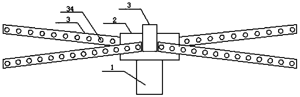
[0032] An aeration pipe for a waste liquid pool for sewage treatment, comprising an air inlet pipe 1 and a hollow cylindrical connection chamber 2, the bottom of the connection chamber 2 is provided with an installation port, and the installation port is adapted to the outer wall of the air inlet pipe 1, and the air inlet pipe 1 The through installation port is plugged into the connection chamber 2 and the upper port of the air intake pipe 1 is located in the connection chamber 2, and the air intake pipe 1 and the installation port are rotationally connected by a sealed bearing; specifically, the air intake pipe is fixedly extended from the bottom of the waste liquid pool, and connected The cavity is then rotatably installed with the upper part of the intake pipe.

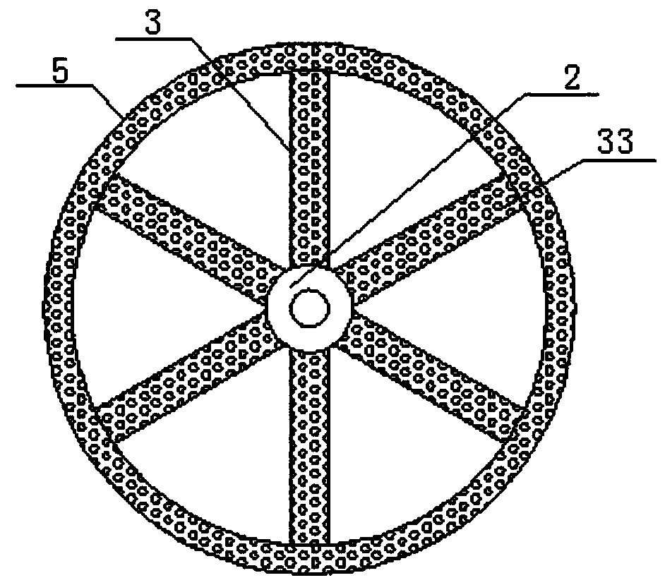
[0033] The side wall of the connection chamber 2 is annularly provided with several connection ports 21, and the connection ports 21 are detachably connected with the aeration pipe 3. For example, the connection por...

Embodiment 2

[0037] Based on the structure proposed in Example 1, the aeration tubes 3 are arranged obliquely, and the inclination directions of two adjacent aeration tubes 3 are opposite.

[0038] Further, it also includes an annular aeration tube 5, which is integrally communicated with the aeration tube 3 to improve the stability of the aeration tube 3; at least one annular aeration tube is connected between the aeration tubes 3 in the same inclined direction. Aeration pipe 5.

Embodiment 3

[0040] Based on the structure proposed in embodiment 1 or embodiment 2,

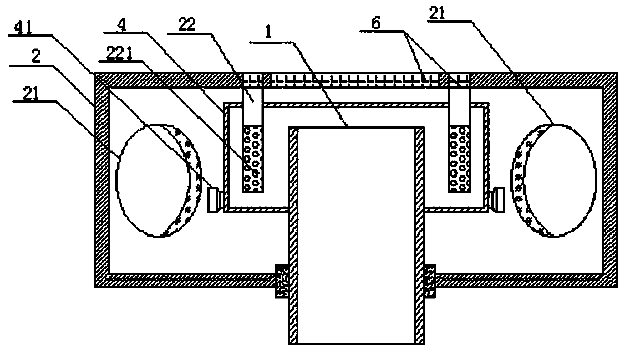
[0041] At least one stirring rod 22 is arranged on the top of the connecting chamber 2, and the lower end of the stirring rod 22 extends into the tank body 4 for stirring and mixing the water purifying agent.

[0042] Further, the stirring rod 22 is a hollow structure for containing solid water purifying agent, a number of communication holes 221 are opened on the side wall of the stirring rod 22 extending into the tank body 4 for mutual communication between the inside and outside, and the connecting cavity 2 The upper end face is hingedly equipped with a sealed chamber door 6, the sealed chamber door 6 is vertically corresponding to the tank body 4 and the stirring rod 22, and is used for putting in liquid water purifying agent and solid water purifying agent. The stirring rod 22 and the bottom surface of the tank body 4 are provided with Sewage outlet (not shown in the figure).


PUM

PropertyMeasurementUnit
Specific surface areaaaaaaaaaaa
Particle sizeaaaaaaaaaa

Abstract

The invention provides a waste liquid pool aeration tube for sewage treatment, and a sewage treatment water purifying agent. The waste liquid pool aeration tube comprises an air inlet tube, a connecting cavity, aeration tubes and a tank body. A partial area in every aeration tube is designed to achieve synchronous rotation pushing, and the rotation direction is adjustable, so the aeration dispersity is greatly improved, and the stirring aeration effect on a waste liquid pool is improved by two times or above; and the structure of every aeration tube has a good promoting effect when used for releasing the water purifying agent, so the utilization rate of the water purifying agent is increased by 30%, and the comprehensive water treatment effect is remarkably improved.

Description

technical field [0001] The invention relates to the technical field of sewage treatment, in particular to an aeration pipe for a waste liquid pool for sewage treatment and a water purifier for sewage treatment. Background technique [0002] Water treatment methods include physical treatment and chemical treatment. Human beings have used water treatment methods for many years. Physical methods include the use of various filter materials with different pore sizes, and the use of adsorption or barrier methods to exclude impurities in water. The most important adsorption method is to use activated carbon for adsorption. The barrier method is to pass water through the filter material, so that the larger impurities cannot pass through, and then obtain cleaner water. In addition, the physical method also includes the precipitation method, which is to let the impurities with a small specific gravity float on the water surface to remove them, or the impurities with a large specific ...

Claims


Application Information

Patent Timeline
IPC IPC(8): C02F7/00C02F3/34C02F1/54C02F1/52
CPCC02F1/5236C02F1/54C02F3/34C02F7/00C02F2201/002C02F2201/007Y02W10/10
Inventor 平步青
Owner 南京思甲宁新材料科技有限公司
Why Eureka
Try Eureka