Rolling crankshaft fillet quick clamping bracket

A crankshaft, fast technology, applied in the direction of grinding workpiece support, clamping, support, etc., can solve the problems of slow operation, high labor intensity, etc., and achieve the effect of reasonable structure, convenient operation and simple manufacture

Inactive Publication Date: 2011-05-25
TIANRUN IND TECH CO LTD
View PDF0 Cites 12 Cited by
  • Summary
  • Abstract
  • Description
  • Claims
  • Application Information

AI Technical Summary

Problems solved by technology

This kind of clamping mechanism is not only

Method used


Image

  • Rolling crankshaft fillet quick clamping bracket
  • Rolling crankshaft fillet quick clamping bracket
  • Rolling crankshaft fillet quick clamping bracket

Examples


Embodiment Construction

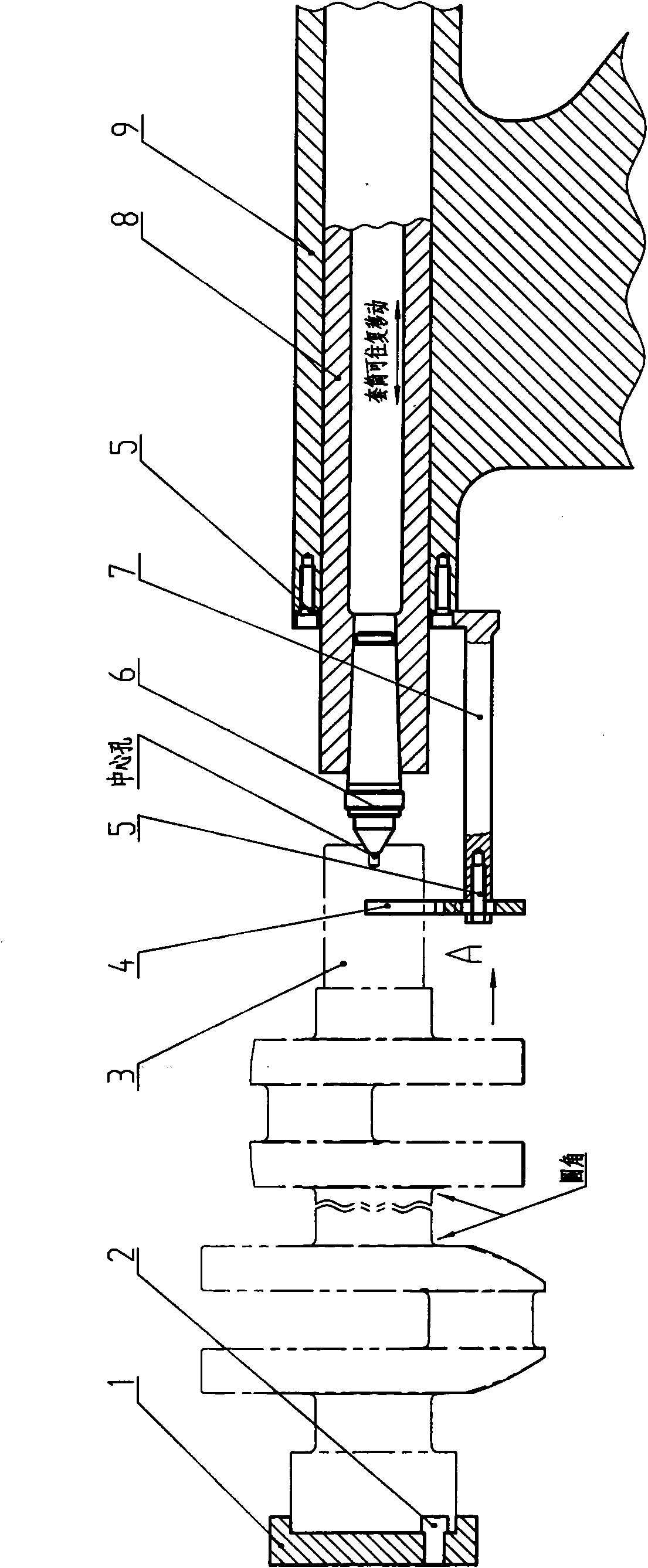
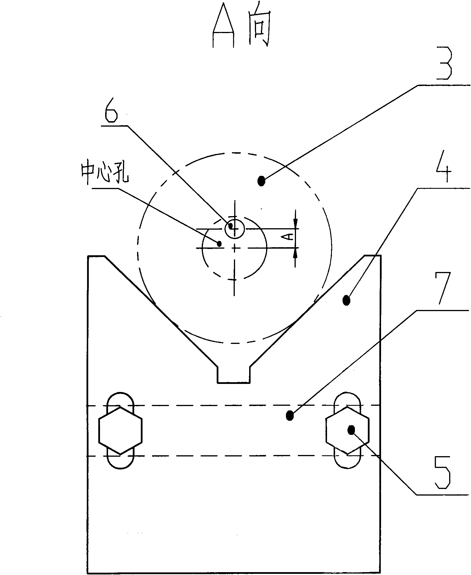
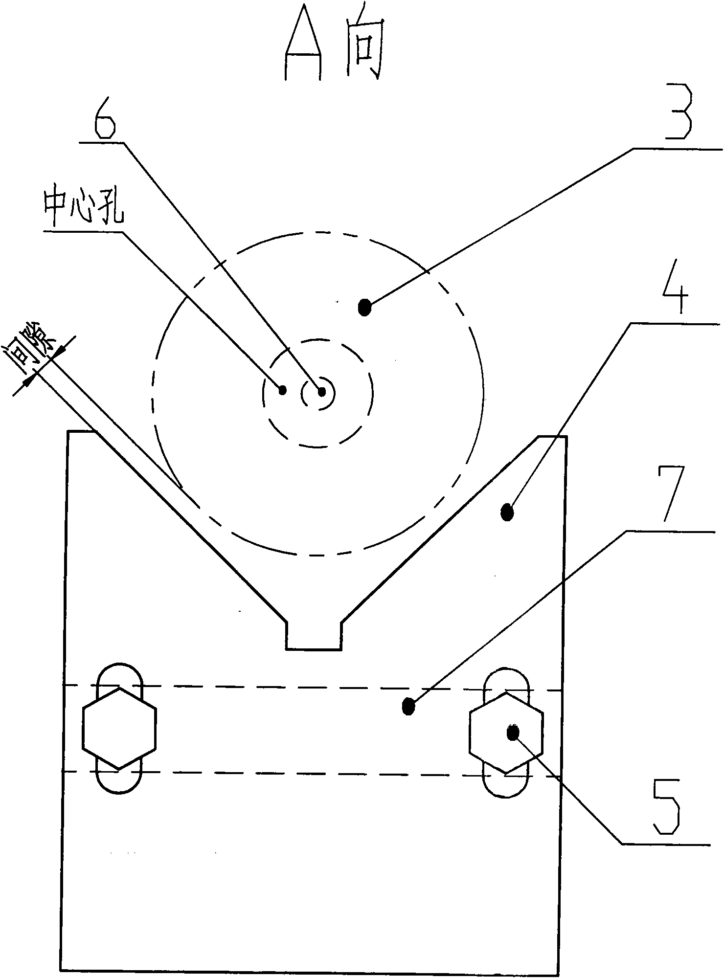
[0014] from figure 1 , figure 2 with image 3 It can be seen from the figure that a rolling crankshaft fillet fast clamping bracket includes drive discs 1 and supporting devices respectively located at both ends of the crankshaft 3 . The crankshaft 3 big end is provided with process location hole, and small end is provided with central hole. Said driving disc 1 is arranged on the big end of the crankshaft 3, on which there is a positioning pin 2 corresponding to the process positioning hole of the big end of the crankshaft, the front part of the crankshaft journal is inserted into the driving disc 1, and the positioning pin 2 is used for circumferential positioning . The driving disc 1 can be fixed on the rotary transmission system of the existing machine tool, driven by the transmission system of the machine tool.

[0015] The supporting device of the present invention is arranged at the small head end of the crankshaft. The supporting device includes a support plate 4,...


PUM


Abstract

The invention relates to a rolling crankshaft fillet quick clamping bracket which comprises a drive disk and a supporting device, wherein the drive disk is arranged at the big-head end of a crankshaft, a positioning pin corresponding to a process positioning hole at the big-head end of the crankshaft is arranged on the drive disk, the supporting device is arranged at the small-head end of the crankshaft and comprises a supporting plate, a bracket body, a core clamper, a sleeve and a tailstock, the bracket body is fixedly arranged at the front end of the tailstock by using a bolt, the tailstock is internally provided with the sleeve capable of moving front and back, the front end of the sleeve is provided with the core clamper corresponding to a center hole at the small-head end of the crankshaft, the supporting plate is fixedly arranged at the front end of the bracket body by using a bolt, and a V-shaped opening for supporting the shaft neck of the small-head end of the crankshaft is arranged above the support plate. The drive disk rotates, the crankshaft rotates with the drive disk, and a rolling mechanism is started so that a crankshaft fillet can be rolled. The invention has the advantages of reasonable structure, convenience of operation, and high clamping speed, and is suitable for clamping various crankshaft rolling fillets.

Description

technical field [0001] The invention relates to a bracket, in particular to a quick clamping bracket for rolling crankshaft fillets. Background technique [0002] We know that at present, the crankshaft fillet is rolled by a crankshaft rolling machine tool. The clamping is to lift the crankshaft, first insert the outer circle of the big head into the drive disc, and then slowly drop it to align the center hole of the small head with the top, and then manually or The pneumatic and hydraulic mechanism pushes the top of the sleeve to compress the crankshaft. This clamping mechanism is not only slow in operation, but also labor intensive. Contents of the invention [0003] The technical problem to be solved by the present invention is to overcome the deficiencies of the above-mentioned prior art, and provide a rolling crankshaft fillet fast clamping bracket with reasonable structure, simple manufacture, convenient operation, fast clamping and wide application range. [0004]...

Claims


Application Information

Patent Timeline
IPC IPC(8): B23Q3/00B24B41/06
Inventor 慈惟红宋文友林治军
Owner TIANRUN IND TECH CO LTD
Why Eureka
Try Eureka