Printing relief plate

A technology for printing letterpress and embossed parts, applied in the field of letterpress printing, which can solve problems such as complex design and marginal effect, and achieve the effects of avoiding marginal effect, improving display effect, and increasing effective display area

Active Publication Date: 2011-05-25
SHANGHAI TIANMA MICRO ELECTRONICS CO LTD
View PDF1 Cites 19 Cited by
  • Summary
  • Abstract
  • Description
  • Claims
  • Application Information

AI Technical Summary

Problems solved by technology

[0007] The purpose of the present invention is to provide a printing letterpress to solve the problem of edge effect and design complexity in the printing letterpress of the prior art

Method used


Image

  • Printing relief plate
  • Printing relief plate
  • Printing relief plate

Examples


Embodiment Construction

[0031] In order to have a detailed understanding of the letterpress of the present invention and enable those skilled in the art to understand the spirit of the present invention more clearly, the letterpress of a specific embodiment of the present invention is described in detail with reference to the accompanying drawings.

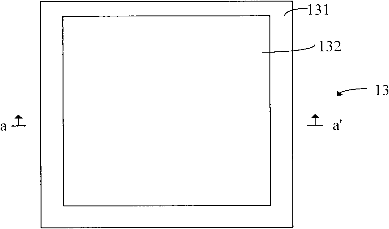
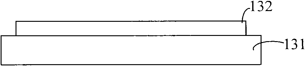
[0032] Figure 6 is a schematic plan view of a printing relief plate of a specific embodiment of the present invention, Figure 7 yes Figure 6 A schematic cross-section along b-b' of a printing relief plate according to an embodiment of the present invention is shown in . The relief printing plate 30 of the present invention includes a carrier base plate 31 and a printing plate body 32 . The printing plate body 32 has a bottom surface 325, and the bottom surface 325 is in contact with the carrying base plate 31, wherein both the carrying base plate 31 and the printing plate body 32 are plate-shaped, specifically, in a certain embodiment of the present...


PUM


Abstract

The invention discloses a printing relief plate, which comprises a bearing bottom plate and a plate body for printing, wherein the plate body for printing is provided with a bottom surface, and the bottom surface is contacted with the bearing bottom plate; and the plate body for printing comprises a central area and a marginal area, a first convex part is formed in the central area, a second convex part is formed in the marginal area, the first convex part is provided with a first top surface opposite to the bottom surface, the second convex part is provided with a second top surface opposite to the bottom surface, and the distance between the second top surface and the bottom surface is smaller than the distance between the first top surface and the bottom surface. According to the printing relief plate, an orientation material can be uniformly printed on a glass substrate so as to prevent a cured orientation film from generating marginal effect and forming a lug in the marginal area, enlarge the effective display area of a liquid crystal display screen and improve the display effect.

Description

technical field [0001] The invention relates to a printing letterpress, in particular to a printing letterpress for printing an alignment film of a liquid crystal display. Background technique [0002] Printing letterpress can be used for various printing. In recent years, printing letterpress has been widely used in the production process of liquid crystal display. Its main function is to use letterpress printing method to print the alignment material On the glass substrate, an alignment film is formed on the glass substrate, so that the liquid crystal molecules can be arranged on the glass substrate according to certain rules. refer to figure 1 , the process of printing the alignment material on the glass substrate is as follows: the anilox roll 11 (anilox roll) rotates counterclockwise, the printing roll 12 (printing roll) rotates clockwise, and at the same time drives the printing relief 13 on it to rotate clockwise, and the glass substrate 14 (glass) moves to the left...

Claims


Application Information

Patent Timeline
Patent Type & Authority Applications(China)
IPC IPC(8): B41N1/12
Inventor 赵剑
Owner SHANGHAI TIANMA MICRO ELECTRONICS CO LTD
Why Eureka
Try Eureka